Maker Pro
Maker Pro

Digital Terrestrial Receiver PSU problem

Good day dear friends.

I have been working with the power supplies of Digital Terrestrial TV receivers for some time and to be honest i do not fully understand how they work. I do know the basics though.

I came across a PSU with a blown fuse. i checked all components and they look ok.

I tested the capacitors with ESR meter and look good. I tested the diodes and also look good. I tested the Coil and looks ok(each part reads 3 Ohms) the varistor also reads infinite so it is ok.

I have disconnected the PSU from the circuit and kept (mains input up to the rectifier bridge) part and it still blows the fuse. when i remove the diodes the circuit works. When i put them back the fuse blows.
I have replaced the diodes with new one twice and still the same. I have also disconnected the varistor and the 400v 22mf capacitor and still... To me it makes no sense. Could anyone help ?

Here is the schematic of the part of the PSU i am working on

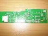
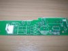
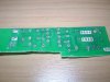
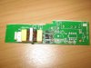
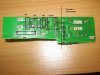
I could also attach photos of the circuit if that could do any good.
 

Attachments

  • trof.png
    trof.png
    5.8 KB · Views: 139
Last edited:

KrisBlueNZ

Sadly passed away in 2015
It's usually the switching device, which is usually a MOSFET. It's connected with its drain (middle terminal) to the bottom end of the primary winding of the main transformer and its source (right terminal) to the negative side of the main smoothing capacitor, often with a low-value resistor in between. It's normally in a TO-220 package, and is mounted onto a heatsink.

Some power supplies use an integrated controller and switch device, which is usually but not always in a TO-220 package (though it may have more than three leads). You can locate it by following the track from the bottom end of the primary winding (the other end of the winding that's connected to the positive side of the main smoothing capacitor).
 
Can you post a picture of the PS board ?
I would replace anyway capacitors, that under high voltage can behave to short.
Is it a switching supply ?
Maybe there can be a short in the secondary ?
 
Kris yes i know. this psu uses a DH321 but the problem i think is not that far from the mains input.

Yes it is a switching PSU

I will post a photo of the PSU later today.

What confuses me is the fact that i use only the circuit shown in the picture (all the other parts removed) and with the diodes on it blows the fuses. Without the diodes i get the 220v right at the input of the "bridge rectifier". A logical assumption would be that the diodes are causing the short. But how ? i test them and they work correctly, not to mention that i replaced them twice.
 
What you mean "only that circuit" ? Isn't it part of the switching circuit ? You have separated it ?
Try to replace the 400V cap.
 

davenn

Moderator
Have you checked the varistor .... they are usually designed to go short cct and blow the fuse
how about those2 caps before the bridge ?

what sort of diodes were you putting in there as replacements ?
and the silly question ... did you put them in the right way around ?

cheers
Dave
 
Last edited:

davenn

Moderator
What you mean "only that circuit" ? Isn't it part of the switching circuit ? You have separated it ?
................

yes the rest of the circuit has been stripped
He, for whatever reason, is only using the input stage

Dave
 
Last edited:
I only use the input stage for now just to figure out why it is blowing the fuse.

And yes i checked the varistors and they are good. I have removed them to further investigate the problem.
I have also replaced the caps before the diodes... Same thing.

Here are the photos...

Can anyone tell me why they use this coil connected that way ? (as shown in picture post 1)
Is it like a smoothing filter combined with the caps ?
 

Attachments

  • P9120008.JPG
    P9120008.JPG
    166.9 KB · Views: 111
  • P9120009.JPG
    P9120009.JPG
    182.3 KB · Views: 154
Last edited:

davenn

Moderator
so what is that huge burn mark between the ends of the centre diodes ?
Its not producing a resistive path is it ?


Can anyone tell me why they use this coil connected that way ? (as shown in picture post 1)
Is it like a smoothing filter combined with the caps ?

yes the caps and inductors are a noise filter .... not for noise coming in on the maims
but to stop the high freq switching noise going out onto the mains

Dave
 
Sure, as stated above by davenn, only issue here should be your de-soldering, you created a shortcut somewhere, check carefully, eventually remove the diodes and see if the shortcut is before or after.
 
Yes there is a huge flux buidup. That might cause trouble but as far as i know solder flux is electrically neutral. (or not for high voltages?)

I will clean it and try it again.

The final test i tried today was to remove all components (caps and coil) and leave the diodes alone. According to the datasheet the 1N4007 can handle upto 1000Volts... Again i got a blown fuse. there must be a short circuit somewhere but why cant the multimeter detect it ? (Note that i use 1.6 Amps fuses)
 

davenn

Moderator
Yes there is a huge flux buidup. That might cause trouble but as far as i know solder flux is electrically neutral. (or not for high voltages?)

Im not talking about all the flux you can see on the solder side of the board, it wont hurt anything
Im talking about that really grey/black looking stuff between the right hand side pins of the 2 centre diodes
it looks like burnt material from arcing


D
 

davenn

Moderator
...................
The final test i tried today was to remove all components (caps and coil) and leave the diodes alone. According to the datasheet the 1N4007 can handle upto 1000Volts... Again i got a blown fuse. there must be a short circuit somewhere but why cant the multimeter detect it ? (Note that i use 1.6 Amps fuses)

OK that doesn't add up because if the coil was removed, then the power couldn't even get to the diodes unless you bridged the gaps with wires

you had better show a photo of that setup both sides of the board :)

Dave
 
Im not talking about all the flux you can see on the solder side of the board, it wont hurt anything
Im talking about that really grey/black looking stuff between the right hand side pins of the 2 centre diodes
it looks like burnt material from arcing


D

Yes i know what you are saying. I removed the diodes from that side of the board and soldered them together on the air but still.

I dont know... iam just about to give up on it. There must be something i am missing here. but what ?

I will remove all parts and clean the board. i will take photos and we will see.
 
After checking the components again i found 2 diodes shorted (the middle ones) and the coil to be "non inductive" (more like just a wire than a coil) according to my digital ESR meter. The capacitors are good.

I know for sure thet the diodes where good. Could the coil have caused the diodes to shortcircuit ?
 

Attachments

  • P9120010.JPG
    P9120010.JPG
    177.9 KB · Views: 136
  • P9120011.JPG
    P9120011.JPG
    154.9 KB · Views: 126
  • P9120012.JPG
    P9120012.JPG
    152.6 KB · Views: 116
Top