Arouse1973
Adam
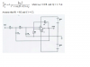
The voltages seem a bit high for 5 and 12 Volt. Your circuit by the way is for a positive and negative PSU? I would be looking for a dual secondary transformer with two bridge rectifiers attached one for each output with separate smoothing capacitors.
I would use high current Schottky barrier rectifiers for the high current 5 volt and standard rectifiers for the 12 Volts.
I would start by working out the ratio of the lowest mains input with respect to the different outputs. You know 180 Volts is your low input and so when the input goes to 240 your stuck with what's on the secondary otherwise it won't work at 180 Volts.
So for the 5 Volt say you needed 6.5 volts peak on the input to the diodes because of the diode drop and regulator drop at max current, remember diodes and regulators drop larger voltages as the current increases. This would be 6.5 / 1.414 =4.59 Vrms 180/4.59 = 39.21:1
So when the voltage on the input is 240, this is then 6.12 Vrms which is 8.65 V peak. Remember this is at max load, the secondary voltage will be even higher maybe 20%, you would need to mention this and consult the transformer datasheet for the regulation information.
Adam