Hello Guys,
This is my first thread here..
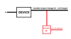
I have a device that contains a circuit like this.

The 1K Potentiometer RV1 is actually a Foot Pedal where the resistance changes when the pedal is pressed and outputs the Voltage to another Device through OUTPUT.
however, The OUTPUT Voltage is set to a fixed Default Value of 1.2V when the pedal is Not pressed and It'll go upto 12V when the pedal is fully pressed.
I need to tap into that output Voltage and connect it to a ESP8266 Analog Input. Since the ESP only works with 3V, I need to convert that output Voltage to 3V.
I tried a voltage divider connected to the output like this.

The Converted Out can be taken down to 3V. BUT the Voltage of the main OUTPUT that goes to the device changes when the Voltage Divider is connected. The Maximum 12V that is supposed to be achieved when the pedal is fully pressed is never reached because the Voltage Divider affects the Total Resistance.
Note that the RV1 Resistor cannot be changed. It is fixed inside a device which is very hard to dismount AND there are 1000s of devices that needs this conversion.
So what are my options? How can I get the Output Voltage of 0 - 12V range of the Device and Convert it into a 0 - 3 V Range ?
Thank you for your support!
This is my first thread here..
I have a device that contains a circuit like this.
The 1K Potentiometer RV1 is actually a Foot Pedal where the resistance changes when the pedal is pressed and outputs the Voltage to another Device through OUTPUT.
however, The OUTPUT Voltage is set to a fixed Default Value of 1.2V when the pedal is Not pressed and It'll go upto 12V when the pedal is fully pressed.
I need to tap into that output Voltage and connect it to a ESP8266 Analog Input. Since the ESP only works with 3V, I need to convert that output Voltage to 3V.
I tried a voltage divider connected to the output like this.
The Converted Out can be taken down to 3V. BUT the Voltage of the main OUTPUT that goes to the device changes when the Voltage Divider is connected. The Maximum 12V that is supposed to be achieved when the pedal is fully pressed is never reached because the Voltage Divider affects the Total Resistance.
Note that the RV1 Resistor cannot be changed. It is fixed inside a device which is very hard to dismount AND there are 1000s of devices that needs this conversion.
So what are my options? How can I get the Output Voltage of 0 - 12V range of the Device and Convert it into a 0 - 3 V Range ?
Thank you for your support!