Maker Pro
Maker Pro

Chinese Hiland 0-30V/Audioguru PSU build (down the rabbit hole)

Thank you very very much Hop. Above and beyond the call of duty. Was up late last night poring over this: http://www.ti.com/lit/ug/tidu020a/tidu020a.pdf

Please just confirm that the guy who wrote this knew his rear end from his arm joint.

Now to find an opamp in my meagre stocks.

Spice simulation came to a dead halt due to my inability to find a CA3140 spice model
 
Last edited:

hevans1944

Hop - AC8NS
Thank you very very much Hop. Above and beyond the call of duty. Was up late last night poring over this: http://www.ti.com/lit/ug/tidu020a/tidu020a.pdf

Please just confirm that the guy who wrote this knew his rear end from his arm joint.

Now to find an opamp in my meagre stocks.

Spice simulation came to a dead halt due to my inability to find a CA3140 spice model
The Texas Instruments application note is "spot on" in accuracy and detail. All you ever wanted to know about comparator hysteresis in one article. TI is my "go to" source for technical information. I have been using their products since the 1960s, first for logic and later (after their purchase of Burr-Brown) for linear devices.

I once toured their facility in Texas in the 1980s to see a demonstration of their infrared FLIR system, integrated with a gunboat-mounted cannon turret (azimuth and elevation) used for drug smuggling interdiction. It was quite impressive watching this thing track automobiles on a freeway about five miles away! Our company was validating this device for export to an un-named (i.e. classified) European country in the 1980s courtesy of the U.S. Government. I was (and still am) impressed with the quality and excellence of TI engineering.

Don't worry too much about finding exact Spice models for op-amps. Use a generic model instead for concept demonstration purposes. Spice was invented for integrated circuit modeling to avoid the expense of re-masking a wafer with design errors. It is way overkill for hobbyist purposes, IMHO. You might try downloading and using Texas Instruments version of Spice: TINA-TI, although Linear Technology's LTSpice is very good too. Most of the problems associated with the use of any Spice program have to do with model initial conditions and how the simulation proceeds from there over discrete time intervals. The devil is always in the details, but try using simple component models first before deciding a more complete (advanced) model is necessary to obtain an accurate simulation. And remember that a simulation is always a "virtual reality," never a substitute for a real circuit with real components.

Hop
 
I did not read the Texas Instruments document you posted but I have seen some serious errors in one of their documents.
 
(H and AG - this long form explanation is intended for the OP)

Not to be picky or anything, but ...

1. A comparator, or an opamp acting as a comparator, does not oscillate when the two inputs are very close to the same voltage. A comparator is at its heart a linear amplifier. It spends most of its life with an output that is outside its linear range, saturated against one power supply rail of the other. Still, a linear amp. When the two inputs are very close together (microvolts), the output no longer is saturated, and is the input voltage multiplied by the open loop gain. Since the input difference voltage is so low it is essentially noise, the output is amplified noise. If the inputs cross each other slowly, as with a slow voltage ramp, the output is saturated low, then full amplitude square wave noise, then analog white noise, the full amplitude square wave noise, then is saturated high. The garbage is amplified noise, not an oscillation.

2. That noise burst does not always happen. If the input rate of change through the transition region (when the device's output is not saturated) is faster than the output stage's slew rate, there will not be a noise burst because the output stage is too slow to keep up. There may be a small hiccup in the middle of the output waveform, but no full-scale transitions. A properly designed hysteresis circuit prevents erroneous output transitions, but it is an added complexity that might be avoided with a little analysis of the signals and devices involved.

ak
 
The experts at National Semiconductor who designed the LM339 quad comparator IC says in its datasheet that it can easily oscillate due to stray capacitance from its output to its input if hysteresis is not added. Simply using an IC socket and attaching resistors to the pins will cause oscillation without hysteresis.

I agree that it will also amplify noise without hysteresis.
 

hevans1944

Hop - AC8NS
I like @AnalogKid's explanation. It also agrees well with the TI graphs that include noise on the input signal. Of course, with just a wee little bit of positive feedback, enough hysteresis can be introduced to overcome noisy inputs. So I am a big fan of deliberate and controlled hysteresis with comparator circuits. Comparator outputs are supposed to be digital, so no time should be deliberately spent in the so-called "linear" region. As @Audioguru pointed out vis a vis the LM339 quad comparator, these (as well as other similar devices) are prone to oscillation because of parasitic feedback paths unintentionally created during actual circuit implementation on a printed circuit board. And I have seen these oscillations occur with "dead bug" and Manhattan construction techniques too when yours truly forgot to include some hysteresis.

As for @Audioguru finding some serious errors in a TI document... well, it happens. But that is why I always advise using multiple sources to verify an "explanation" you are trying to understand. It has been my experience that, for the most part, application notes written by the major semiconductor companies contain valid information. I do tend to trust TI documents, but not blindly. I would appreciate it if @Audioguru would cite the TI document he found that contained serious errors. Errors are sometimes corrected in later published versions, but without knowing the publication history it is difficult to track corrections. Microchip, for example, recommends that you always download the latest version of their documentation from their website to avoid being misled by outdated and/or erroneous documents.
 
I would appreciate it if @Audioguru would cite the TI document he found that contained serious errors. Errors are sometimes corrected in later published versions, but without knowing the publication history it is difficult to track corrections.
I found the error made in a TI document. If the opamp has gain more than 1 then the output would be saturated as high as it can go.
Instead of fixing the error, TI deleted the entire document!
 

Attachments

  • TI error.png
    TI error.png
    29.2 KB · Views: 140

hevans1944

Hop - AC8NS
Instead of fixing the error, TI deleted the entire document!
As well they should have! Here is a 
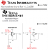
link to the original application note, which must have been created shortly after TI absorbed Burr-Brown on June 21, 2000.

I had not seen this TI application note until I went looking for it as a result of @Audoguru's response to my query. While reading the entire note, I got an uncomfortable feeling about it. There are several typographical errors as well as the circuit error discovered by the Audio Guru. Closer reading might even reveal more circuit errors. What I found most peculiar was the writing style. It just didn't "feel" right.

I suspect management in TI marketing decided that, now that Burr-Brown was a part of TI, someone should write a TI branded application note about how to use op-amps with single-source power supplies. Unfortunately, it does not appear that TI bothered to ask anyone at Burr-Brown for help with this, assigning the project instead to a lower-level, recently hired, TI engineer/tech writer/application engineer. This engineer then attempted to gather a hodge-podge of information from previously published Burr-Brown literature and assemble it into a "vague and hard-hitting" application note entirely useless as a guide to actual real designs. Marketing guys are good at this sort of obfuscation, but the author, Bruce Carter, only stayed with TI for six years. It could have been written by a disgruntled Burr-Brown employee, acquired as part of the merger, who was on the way out the door after the merger, a kind of "busy work" project until all the details of the merger were worked out and duplicated job positions in the two companies were eliminated.

Whatever the history behind it, I am sure it was a huge embarrassment to Texas Instruments. It may still be, because thirteen years later TI SLOA058 was still causing problems, as this thread from the TI E2E™ Community illustrates. Scroll to near the end, where Bruce Trump, a long time TI employee (now retired) and a Community Member with a Guru rating stated, at 4:26 AM on March 8, 2013: "I suggest that you not try to use SLOA058 document. It contains too many errors." Emphasis mine.

During most of the 20th Century, Burr-Brown (and a few others) was the the "go to" source for high-performance op-amps and instrumentation amplifiers. Integrated circuits, and laser trimming during production, turned a niche market into a highly competitive international market as op-amp applications exploded. Burr-Brown managed to stay abreast of most of the changes, but it had nowhere near the financial and marketing clout of Texas Instruments, so a merger was probably in the best interests of both companies at the time. Most analog designers (including yours truly) had an extensive collection of Burr-Brown application notes that were invaluable for practical circuit design. In case you missed it, most (maybe all) of these notes are now available for download as zip files here.

Lest anyone think Burr-Brown was the analog giant in shining armor who helped wrestle TI into the analog market, be aware that TI was already making "pretty good" integrated circuit op-amps and other hybrid analog/digital products such as integrated circuit DACs and ADCs when the merger occurred. The two merged companies had plenty of competition from the likes of Analog Devices, Linear Technology, Microchip and Motorola, just to name a few.
 
hevans, audiog, ak, thanks so much for the informative lesson in hysteresis. I have learned a lot.

Progress report:
I have started populating the board with the components that I have managed to acquire so far. Finding components in the sharp end of Africa has been a headache so far.
Ag, I strongly suspect that farnell here is just a web presence and that any components that you order is coming from overseas with accompanying transport costs.

build1.jpg
I'll be getting the new improved transformer this weekend and the TLE2141's should be here next week.

Audioguru, I assume Q4 and Q5, the 2N3055's, should be heatsinked? I must say, I was a bit surprised that the 3055's are only available in TO-3 package as far as I can tell. They have forced me to rethink the cpu heatsink as the heatsink, as mounting them on there will interesting.
 
Regarding the 2N3055's:

I found some ancient one's of unknown history. I scored a whole bunch of components from a car radio shop that operated in the 80's.

Ran them through my chinese esr tester:

B Uf
1 80 494
2 68 503
3 11 517
4 153 545
5 20 520
6 86 557
7 67 508

Can someone please help me pick 2 good un's. No idea what the B and the Uf stand for
 
Audioguru, I assume Q4 and Q5, the 2N3055's, should be heatsinked?
If the transformer is 28VAC then the fully loaded positive supply is +37.6V. If the current of the project is set to 3A and the output is shorted then the output transistors dissipate 3A x 37.6V= 112.8 of heat or 56.4W each.
On the datasheet of a 2N3055 it says it will be at its maximum internal allowed temperature of 200 degrees C (extremely hot !) with its case cooled somehow (liquid nitrogen?) to 25 degrees C when it dissipates 115W.
Its thermal resistance from its chip to its case is 1.5 degrees C per Watt and an insulator with thermal paste might add 1 degree for a total thermal resistance of 2.5 degrees C per Watt. If the ambient is 30 degrees C and you do not want its chip to exceed 150 degrees C then with it dissipating 56.4W its heatsink must be huge with fins and probably with a fan. The heatsinks are manufactured with a thermal resistance rating but I don't have time today to calculate it.

I must say, I was a bit surprised that the 3055's are only available in TO-3 package as far as I can tell. They have forced me to rethink the cpu heatsink as the heatsink, as mounting them on there will interesting.
I do not know if a cpu heatsink can cool 56.4W of heat.

Your esr tester tests capacitors, not transistors. You need transistors that have detailed datasheets for you to compare with the datasheet of a 2N3055. Maybe you can find smaller TIP3055 transistors that are in a smaller plastic case with a metal tab and use three or four in parallel?
 

Attachments

  • TIP3055.png
    TIP3055.png
    9.4 KB · Views: 124
I'm quite happy using the 2N3055's. Will heatsink them. I think it's very unlikely that I will ever need 3A @ 30V. Just need to find out if any of them is usable as I know nothing about their history.
 
Due to the size of cap C1(12000μf 63V) I will have to move it off board. Does it matter if the cap is now connected via 100mm (4") long cables?
 
Put a 0.1uF ceramic capacitor on the board then your 12000uF capacitor will be fine with 18AWG wires 100mm long. Imagine how much ripple there was with an output of 3A when the capacitor was the original little 3300uF.
A Chinese unbranded 3300uF would be 1500uF or 1000uF? Have you seen the video of a big fake Chinese capacitor with a real tiny capacitor inside?
 

hevans1944

Hop - AC8NS
Due to the size of cap C1(12000μf 63V) I will have to move it off board. Does it matter if the cap is now connected via 100mm (4") long cables?
Depends on how big (diameter) the cables are, how much charging current and discharging current flows during the AC line cycle, how much voltage drop as a consequence thereof you can tolerate, how important the minor added inductance of the connecting cables are... yada, yada, yada. For the power supply you are building, it probably doesn't matter as long as you use heavy-gauge wire, say 18 AWG or larger, for the two cables. OTOH, don't go stringing low-voltage "bell wire" (20 to 28 AWG) for this. Follow the advice of the Audio Guru (post #34) and add a small 0.1 μF ceramic disk capacitor in parallel (through the two cables) with your largeish reservoir energy storage capacitor, said disk capacitor to be located at the printed circuit board end of the two cables.

Consider using insulated, braided, copper strap. This can be easily salvaged from short lengths of coaxial cable by removing the insulated inner coaxial conductor, pulling it out with a pair of pliers, leaving just the braided shield and the plastic outer jacket of the original coaxial cable. This works well for soldered as well as crimped ring-terminal connections. You can flatten and then poke a hole in the braid for screw-terminal connections. If you do that, it's a good idea to tin the end with solder to keep the braid from unraveling after installation.
 
I like that idea of yours hevans, would never have thought of that.

This idea of small cap in parallel is new to me. Can you give me a short description of how this works or maybe just a weblink.
 
This idea of small cap in parallel is new to me. Can you give me a short description of how this works or maybe just a weblink.
When a filter capacitor is connected with a length of cable then the resistance and inductance of the cable causes poor high frequency filtering to the circuit which might cause voltage spikes or oscillation. The 0.1uF ceramic capacitor on the pcb provides excellent high frequency filtering that is probably needed.
 

hevans1944

Hop - AC8NS
I have got some of this wire, should I go thicker? : http://www.mantech.co.za/Stock.aspx?Query=352M0024and
This wire appears to be adequate.

Have you seen the video of a big fake Chinese capacitor with a real tiny capacitor inside?
Missed that one, but I saw images of an alleged Li-Ion battery stuffed with an inert filler instead of a real battery component. Lots of these fake as well as counterfeit batteries out there, all available at very low prices from Asian vendors. If something seems to be selling for waaay below the price of "competitive" products, be afraid... be very afraid.
 
Top