Maker Pro

Bench power supply upgrade

I've checked every solder joint and touched any that didn't look perfect with the tip of the soldering iron to make sure. They are all nice & shiny.

VD2 tests OK according to my meter. I checked several times to make sure and it is consistently 0.644V in one direction and 0V in the other.
If it was in backwards I would expect the red light to turn on every time I turn it on but that isn't the case. It is correct according to both the drawing and the marking on the board too.
BTW: The output of OP1 isn't always -4.1V. If I turn the voltage all the way down before turning the power on the output of OP1 varies between 0.04V and 22.66 (most of the time)

And just to make you happy I replaced R8 with a 1.5KΩ with the other end tacked to the end of R5 (= -5.1V ). It made absolutely no difference.
 
When you have the problem of no variable output voltage and the output of OP1 is -4.1V, is the red LED turned on (when it should be turned off)?

The correct R8 allows you to to turn down the voltage to minimum and adjust R7 for an output of 0.00V.
 
Measured relative to the negative of the 24V supply I have:
-4.04V between and the output of OP1 and it doesn't change when I turn the pot.
0V at the other end of R3 (= base of VT2) with no change when I turn the pot.
-0.661V at the emitters of both VT1 and VT2 with no change when I turn the pot (the difference between this and the -0.659V at the output is the drop across R6).
All of the above applies only while the light is on and the output is about -0.66

When the light is not on the output voltage is 0V when the voltage pot is turned all the way down. It was zero when R8 was connected per the kit and it is still zero with R8 connected to -5.1V.

I haven't tried it with a load yet but I think when the light doesn't turn on it works properly. If we can figure out why it only works when the voltage is turned all the way down before I turn it on I think it will be OK.

Chinese electronics products tested says
Switching on the power supply
The first thing you notice is that the power supply sometimes starts up in CC mode and provides an output voltage of 0 V. The LED lights up and the circuit does not work. Fortunately, it helps to switch off the mains voltage and then switch it on again. This strange action is probably due to the unusual circuitry used to generate the internal reference voltage.
I wonder if my problem could be related to that?
 
It is OP2 that senses current in R6 and if the current is higher than the setting of the current pot then the output of OP2 goes negative which turns on VT4 and the red warning LED, and turns down the output voltage through VD2 and OP1.

Your problem occurs when the voltage setting of R13 is above minimum when the power is turned on.
But the setting of R13 has nothing to do with OP2 detecting too much current in R6 so maybe the pcb wiring wrongly connects them together.

OP3 makes the +10.2V reference voltage. The setting of R13 also has nothing to do with OP3 working or not when the power is turned on. If the output of OP3 is less than +10.2V when the power is turned on then your problem will occur. Then measure the output voltage of OP3 when your problem occurs. Again, the output voltage of OP3 when the power is turned on has nothing to do with the setting of R13, but it will happen if R13 has a short circuit inside it.

I agree that the circuit of the OP3 reference is unusual but I think it should work fine if something else (a short circuit inside R13?) does not mess it up.
 
Another couple of hours making my head swim in the shop but I think I may have learned something.

1) While Googling for similar symptoms I found a bunch of threads about these kits on All About Circuits, including this one.
https://forum.allaboutcircuits.com/...-3a-power-supply-question-offset-null.177257/
Since adjusting R7 doesn't seem to make any difference I got curious and checked the resistance between the Offset pins of OP1 and it is 100K (=R7). Those pins are not connected on OP2 & OP3 and the resistance between them is infinity.
It looks like my unmarked chips are fakes with nothing between the Offset pins.
Could this cause my problem?
Like Aztecboy I happen to nave a 741 on hand. He asked if it would be a suitable substitute but didn't get an answer. Would it?
Could that cause my problem?

2) As far as I can tell there is no short in R13. Swapping it with R21 made no difference.

3) I measure 10.2V between the output of OP 3 and output negative when the project is working.
Here's where it gets interesting: When the light is on and I attempt to measure the voltage with my Aneng M118A auto ranging meter the light turns off and the project starts to work. After a bit of experimenting I found that this happens as long as the voltage pot is in the bottom half of its range but if I turn it higher than halfway before turning the power on the light stays on when I connect the meter and the voltage between the output of OP3 and negative varies between 0V when the voltage pot is turned down and -0.562Vwhen it is turned up.
I also found that if I set the meter to voltage the light stays on when I connect the meter so whatever is causing it to start working has to do with what the meter does while figuring out what it is measuring.

4) While I was tracing the circuit to make sure it matched the schematic I discovered that R22 is not there. I tried adding it but it made no difference.

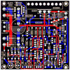
BTW: Here is the x-ray image of the board from Chinese electronic projects tested with the part values &c copied from the image of the board and overlaid and the OP numbers added for reference
Board Xray with values.GIF
 
I forgot about cheap Chinese fake parts. I never buy Chinese junk online.
OP3 has no negative supply so you should measure its output voltage from its output to the 0V output.
What was the meter wrongly set to measure when you switched it to measure voltage?
I am sorry that I do not have time to check the pcb wiring.
 
The meter is in full auto ranging mode when you first turn it on. It automatically detects whether there is a resistor or voltage source (AC or DC) and measures it. It detects so fast that I almost never bother pushing the power button to cycle through the ranges unless I'm checking a diode or capacitor. Or a voltage that might be zero.
I suspect that when it is determining what it is connected to it might produce a small voltage and that could be what triggered the project to clear the overload.

I didn't expect you would trace the board but I posted it in case you wanted to (also, maybe someone else who needs in the future it will find it here).

What effect would leaving R22 out have?

Could the fact that the offset adjustment is missing from OP1 be what's causing it to go into overload mode when turned on?

Do you think replacing OP1 with the 741 might fix the problem?
 
The very old original circuit never had a not needed resistor that the Chinese used for R22. It is simply parallel to the voltage setting pot R13. You can replace the opamps with 741 opamps but the 741 uses 10k for R1 and a piece of wire for R8 connected to the negative supply.
 
R1? That's the bleeder for C1 (smoothing cap for rectified AC).

I tried unsoldering OP3 but I was afraid of frying the traces so I ended up clipping all of the leads, then dealing with each hole 1 at a time. There's s socket on the board now with the 741 plugged into it.

The LED still lights if the voltage pot isn't turned all the way down when I switch the power on.

I set R7 close to the middle before I plugged in the 741 and soldered the the 270KΩ R8 back in. When I turned the voltage down and switched the project on I measured -0.001V at the output and was easily able to adjust it to 0.000V so that part of the circuit is working even connected per the kit.
When I turn the volume pot all the way up I measure 22.55V at the output. It was 21.75V on Saturday (post #77) with the fake opamp.

Nothing else has changed significantly.

I will remove R22 from the schematic.
 
When OP3 was changed to a 741 opamp then you still have the problem of the led lighting when it shouldn't and no output voltage control after power-up when the voltage pot isn't turned all the way down at power-up? The output of OP3 should always be at +10.2V and the output of OP2 controls the LED. Maybe OP2 is bad.

Sorry, I meant that the datasheet for the 741 opamp shows a 10k offset trimmer (the Chinese R7) and a piece of wire to the negative supply (for the Chinese R8). They should allow you to turn the voltage to minimum with R13 and adjust R7 for an output from the project of 0.000V. Some good quality TL081 or LM741 opamps have an offset of +/-0.015V, and opamp OP1 has a gain of 3.07 so the output offset could be as high as +/-0.046V for the offset trimpot to null.

You still need to reduce the value of R9 so that the output of opamp OP1 does not saturate as high as it can go when you turn the voltage pot up to maximum and the output current is as high as it can go. The max regulated output voltage is about 5V less than the max loaded input voltage.
 
When OP3 was changed to a 741 opamp then you still have the problem of the led lighting when it shouldn't and no output voltage control after power-up when the voltage pot isn't turned all the way down at power-up?
Yes.

The output of OP3 should always be at +10.2V and the output of OP2 controls the LED. Maybe OP2 is bad.
If I turn the voltage pot down before turning it on the output of OP3 is always 10.2V
When the LED is on the output of OP3 varies between 0V when the voltage pot is turned down to -0.568 when it is turned up.(This was -0.562 before I replaced OP1)

Sorry, I meant that the datasheet for the 741 opamp shows a 10k offset trimmer (the Chinese R7) and a piece of wire to the negative supply (for the Chinese R8). They should allow you to turn the voltage to minimum with R13 and adjust R7 for an output from the project of 0.000V. Some good quality TL081 or LM741 opamps have an offset of +/-0.015V, and opamp OP1 has a gain of 3.07 so the output offset could be as high as +/-0.046V for the offset trimpot to null.
Ah, that makes sense. It seems to have nulled OK the way it is so I think I'll leave that part alone for now.

You still need to reduce the value of R9 so that the output of opamp OP1 does not saturate as high as it can go when you turn the voltage pot up to maximum and the output current is as high as it can go. The max regulated output voltage is about 5V less than the max loaded input voltage.
The kit schematic shows 56K for R9. I currently have 36K there per your recommendation. Should it be even lower than that?
 
The LED is driven by opamp OP2, not OP3. OP3 is the 10.2V reference that feeds the 10k voltage pot and the R23 56k resistor (I think its value was reduced so that the max current from the project is 2.5A) that feeds the 10k current pot so it is not possible for the slider of the 10k voltage pot that feeds a 27k resistor R12 and 56k to reduce the 10.2V down, unless the voltage pot's slider shorts to ground when you turn it. The pcb wiring looks OK.

With R9 as 56k then the OP2 gain is (36k/27k) + 1= 12.3333 then the max project output will try to be 10.2 x 2.3333= 24.0V which will happen with a 2.5A load only when the input voltage is 24V + 5V= 29VDC fully loaded. If your input is only 24VDC then the max regulated output is about 19VDC and any voltage set higher will be unregulated and change with load current and have some hum on it.
In that case you must change R9 to 24k so that a max regulated output at 2.5A is about 19V.
 
The LED is driven by opamp OP2, not OP3. OP3 is the 10.2V reference that feeds the 10k voltage pot and the R23 56k resistor (I think its value was reduced so that the max current from the project is 2.5A) that feeds the 10k current pot so it is not possible for the slider of the 10k voltage pot that feeds a 27k resistor R12 and 56k to reduce the 10.2V down, unless the voltage pot's slider shorts to ground when you turn it.
And yet it does, but only when the LED is on. And as far as I can tell no part of the pot shorts to anything it isn't supposed to. (The pot is mounted on plastic so it can't short to the chassis either.)
I wonder if an intermittent problem with OP3 or one of the components connected to it could cause this problem?

BTW: R23's value was increased to 80K to limit the current to 2.4A.

With R9 as 56k then the OP2 gain is (36k/27k) + 1= 12.3333 then the max project output will try to be 10.2 x 2.3333= 24.0V which will happen with a 2.5A load only when the input voltage is 24V + 5V= 29VDC fully loaded. If your input is only 24VDC then the max regulated output is about 19VDC and any voltage set higher will be unregulated and change with load current and have some hum on it.
In that case you must change R9 to 24k so that a max regulated output at 2.5A is about 19V.
24V output is my goal.

The supply voltage is currently 24V + 5.3V but I can adjust the 24 higher if needed.
 
The output of opamp OP3 should always be about +10.2V but you said that it drops to 0V or -0.5V sometimes when the power is turned on. Its output low is about +1V so I do not see how it can be 0V or -0.5V. The setting of the voltage pot has nothing to do with the OP3 output voltage if the pot is not shorted.

The output of opamp OP2 should be a positive voltage when the project's output current is less than the setting of the current pot because of the small voltage across R20 from OP3. Then the red LED is turned off and VD2 does not cause the output of OP1 to go low. But if the output of OP3 is much less than +10.2V then the input offset voltage of OP2 can cause its output to go low, turning on VT4 and the LED, and causing the input to OP1 to go low which causes the project's output voltage to be near zero volts.

The +10.2V reference voltage should have been simply a 10V zener diode powered from a resistor. then OP3 and its 3 resistors are not needed.
Maybe the OP3 circuit was used because a 10V zener diode has its voltage rise a little when it warms up but a 5.1V zener diode's voltage is less affected by temperature.
 
I think I have either figured it out or caused another problem. Or both.

I got thinking about your idea that the voltage pot might have a short so I tested it again, this time with an analog multimeter so I see if the needle jumped while I turned the knob (sometimes digital meters just can't tell you what you need to know). The pot is definitely good.

So I studied the circuit for a while and decided to see what would happen if I turned it on with the pot disconnected and the LED didn't light (no surprise).

Next I lifted one end of R12 and the LED did not light on no matter where the pot was set. Hmmm...
So I connected a 10K resistor instead of the pot and the LED lit when turned the power on. Hmmm.... again

At that point I decided to try measuring the output of OP3 again. As before, the LED turned off when I connected the meter except this time the meter was set to volts. I repeated this several times and noticed that if I touched the meter's red lead to OP3's output (actually to the cathode of VD6 because there's nothing near it) before I touched the meter's black lead to output negative the LED turned off. Hmmm... one more time.

After repeating that several times I tried touching it with a test probe that wasn't connected to anything. Several times. Nothing happened the first couple of times but the 3rd time there was a soft pop and the smoke escaped from OP3.

So either OPs was defective or I killed it trying to figure out what the problem was. I guess the next step is to order a few replacements and put the project on hold until they get here.
 
The first fake TL081 had offset pins connected to nothing.
The second one blew up.
I wonder if your third one has a third problem?
 
None of them have anything connected to the offset pins. But I was thinking more or less the same thing.

It's probably best to use TL081s for all 3 (instead of the 741) while I'm at it too.
 
Top