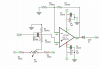
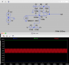
I tried to design a schematic with opamp to add and select through a pot, the dc-offset at a sine wave. I would like to have unity gain in exit but my schematic has a lot of gain. Why? I can't figure out , which is the formula for gain in this schematic? Thank you

[mod note: added full image to post]
[mod note: added full image to post]