Yes, IMO.Is this right?
-
Categories
-
Platforms
-
Content
Yes, IMO.Is this right?
OK. I think if we drive T3 and T5 with two separate transistors and modify the code accordingly we can prevent this. Is this right? (In this case we will use 4 instead of 2 microcontroller pins).
.. how should I incorporate these changes into the circuitary? (I'm asking you to make this idiot proof for me... high shoot-through current.
I don't understand this. If you already are running 5 V power and GND from somewhere to each motor, then why is one more wire "impossible". Or, what about a circuit (actually, 70 circuits) near the Arduino that sends reversing power out to the motors on 70 2-wire links?Each motor is so far apart from one another that controlling them with one Arduino or Raspberry Pi would be impossible
Hi AnalogKid,I don't understand this. If you already are running 5 V power and GND from somewhere to each motor, then why is one more wire "impossible". Or, what about a circuit (actually, 70 circuits) near the Arduino that sends reversing power out to the motors on 70 2-wire links?
Arduino -> 70-stage shift register ->-| -> 70 2-transistor power switches -> 70 2-wire links
5 V supply -> -5 V converter ->-|
ak
I might have missed this back in the thread - what is the running current for one motor at 5 V?
Also, does the running time for each motor have to be settable in precise increments, or is an adjustment pot acceptable?
If the running current is less thean 100 mA and a pot is acceptable, then each motor can be driven by a pair of 555's (or one 556). No PICs, no code.
ak
Hello BobK,Do all of these motors need to operate synchously. If so, it is much more complicated.
Bob
I don't know what "running at that same time" could mean, other than they are synchronized.All of the motors will be standalone and not connected with one another - although they will be running at that same time.
In the main loop you will read the ADC3 input. It will give you a value between 0 - 1023. You need a period between 20 - 6000 seconds. So you will map the reading to this range.
You will use delay(x) where x will be a number between 20000 and 6000000
Hello Sumeryamaner,
thanks for your help. I've spent a lot of time on this but I am unfortunately slightly flummoxed - It isn't working and I'm wondering what I'm doing wrong.
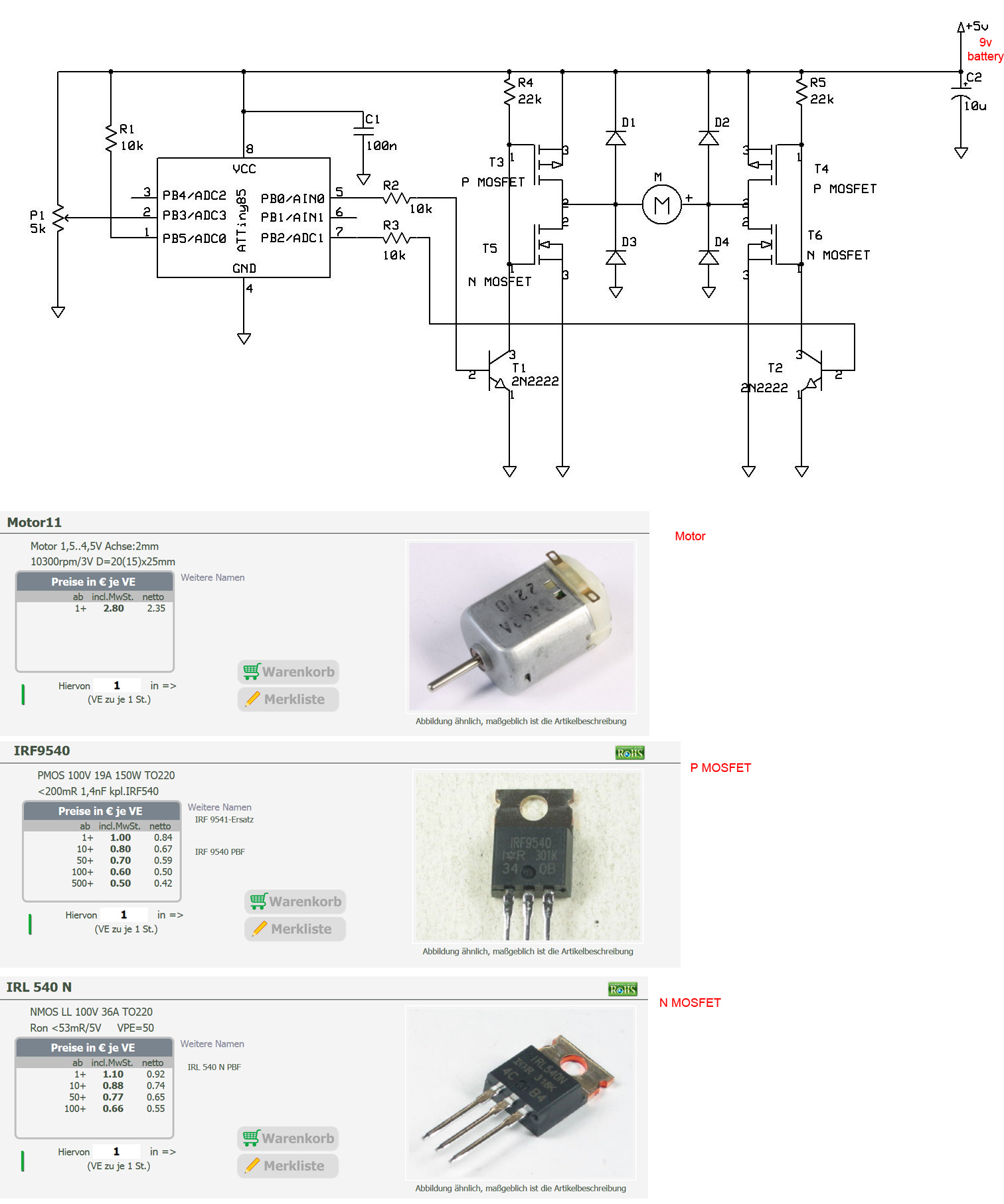
I think I know what I've done wrong and that is the coding - I've got PB0, PB2 as outputs and when I test them seperately I can make them flash LED bulbs ; ) but I couldn't work out how to code in the ADC3 input:
Basically I've just made a blinking lights code and couldn't work out the coding that you suggested.
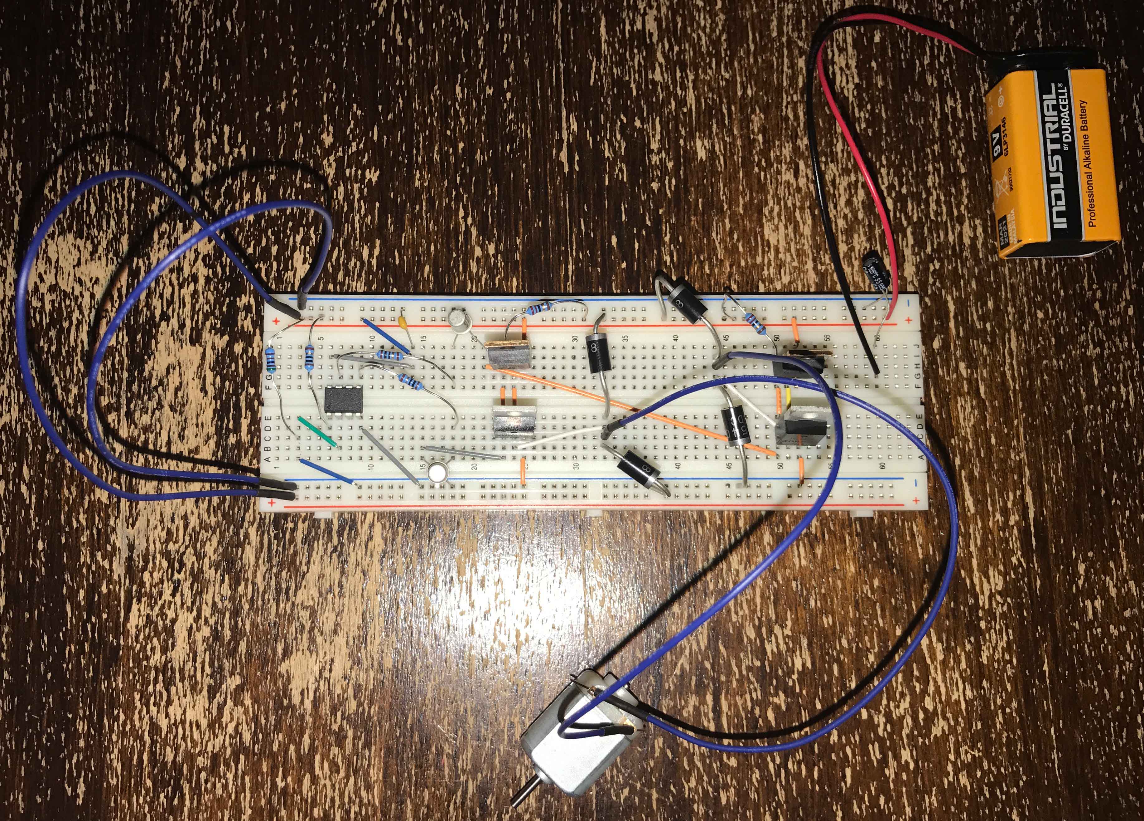
This is the breadboard I built (I think quite faithfully to what you suggested):
![]()
I was a bit of a fool in my original description, I said 5 volt power source - I meant 9V.
Here is your schematic again with info about the motor and the Mosfets that I used:
![]()
Can you see where I am going wrong (if it isn't the coding - which I am sure is the problem)? And if you can, could you help me and tell me how to fix it?
Many, many thanks in advance!
Kind regards,
Euan
First of all there is a very big problem. The supply voltage... you have applied 9 V. Why?
...
About the code... (Assuming you are using Arduino IDE)
Declare an integer variable. For example "int x;"
Declare a long variable. For example "long y;"
Now in the main loop:
x = analogRead(3);
y = map(x, 0, 1023, 20000, 600000);
Then use delay() function for the control of the intervals.
digitalWrite(0, !digitalRead(0));
digitalWrite(2, !digitalRead(2));
delay(y);
As ever - thank you so much!
Luckily I didn't burn out the microcontroller (it can still make the LED's blink : ) but I have followed your advise and gone down to 5 volts powersupply. There is no good reason for the 9volts other than that I had a 9 volt battery laying around - silly mistake.
It is unfortunately still not working. I am using Arduino IDE. How does this code look - have I made another silly mistake?
void setup() {
digitalWrite(0, HIGH);
digitalWrite(2, LOW);
}
void loop() {
int x;
long y;
x = analogRead(3);
y = map(x, 0, 1023, 20000, 600000);
digitalWrite(0, !digitalRead(0));
digitalWrite(2, !digitalRead(2));
delay(20000);
}
Thanks for your help and patience!
It is unfortunately still not working.