Maker Pro
Maker Pro

Battery Tender Charger Model #021-0128 Blown Component?

Attached picture shows component U4 lower middle of frame appears to have let go of its magic smoke. I think U is abbreviation for integrated circuit. Looks pretty small for an IC, regardless, the part number is not readable. Any suggestions?
 

Attachments

  • 20210513_153359.jpg
    20210513_153359.jpg
    289.9 KB · Views: 18
The last battery charger I repaired just needed a voltage regulator to fix it. That regulator was a large component especially compared to this one and I could still read the component numbers. It was off a heavy but cheap Harbor Freight charger that only had several components. This battery charger is much more complicated/expensive and I have never worked on components this small. The harbor freight one could handle much more amps and this one is just a 1.25 amp trickle charger (pic attached). What would you all suggest for a possible replacement? Regulator voltage would need to be closely spec'd to original but I am not trained in electronics so could only guess at say 13V and maybe 2 amps capacity? Any advice on removing/replacing this small would also be very much appreciated.
 

Attachments

  • 20210513_190214.jpg
    20210513_190214.jpg
    276.9 KB · Views: 8
Last edited:
Voltage regulator perhaps.
Just looked at the board closer. U1, U3 & U5 are multilegged ICs. Could not find U2 but suspect it could be one of the two components buried in white silicon? The mystery dead U4 does have only 3 or possibly 4 legs like a VR? - maybe some type of hybrid Voltage Regulator?

note: just to get at circuit board i had to drill out four rivits. short of someone posting pic of same board (not likely if have to drill), is it even possible to know what this fried component is?

why can't companies make em like they used to. to last and when eventually fail, fixable???????
 
Last edited:
Fourth leg, possibly centre, usually common with top tab.
U1 is a microcontroller and would work on 5v.
U3 I cannot see the numbers and U5 is possibly a switcher for the power supply.

Can you post a photo of the other side of the board please.
 
Fourth leg, possibly centre, usually common with top tab.
U1 is a microcontroller and would work on 5v.
U3 I cannot see the numbers and U5 is possibly a switcher for the power supply.

Can you post a photo of the other side of the board please.

Absolutely can. Will try to post whatever you ask for - thank you!
U3 is AS324M-G1 described as a LOW POWER QUAD OPERATIONAL AMPLIFIERS
Using different camera angles I think 4 of the numbers on fried component may be 814j. Unfortunately, I just scraped the burnt part off thinking it may reveal more but appears now worse. Will try to post a better picture.
 

Attachments

  • 20210513_215233.jpg
    20210513_215233.jpg
    310.9 KB · Views: 14
Last edited:
Unfortunately, I have to resize picture to post, then clairity is lost so can't post. first 3 letters are definateley 814. Might be able to find 4th number with natural daylight but not very optimistic.
 
Last edited:
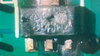
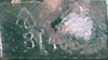
Looked up the S814 series of cmos voltage regulators and there is a 3 pin type with SOT-89-3 case same as yours BUT....... without the suffix numbers there is little chance of finding the correct one.
They range in output from 2v up to 6v.
pdf link below.....
Appear to be low dropout regulator meaning the difference between the input and the output can be small and the regulator will still operate whereas standard regulators will cease with around 2v difference.

Measuring the input voltage may show an indication of voltage required.
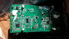
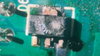
Noticed the 2 electrolytic caps close by originally and voltage markings on them will be above the regulated level so not much help there.
The quad chip operates over a range of 3 to 36v so that's no help either.
Only possibility would be original thoughts with the microcontroller operating voltage of 5v.

That would be about the limit of any help from a distance I'm afraid.

https://digchip.com/datasheets/parts/datasheet/432/S-814-pdf.php
 
The explosion happenned nearest the last two digits. This is the best picture I could find, hoping your can decipher..
 

Attachments

  • 20210514_121045.jpg
    20210514_121045.jpg
    153.9 KB · Views: 12
Afraid not.
You'd need Scotty off "Star Trek" with a particle reconstruction ray to decipher that lot.
About the only chance would be to peek inside a working unit.

If you have any experience in and around mains connected gear you might have one chance in a thousand of getting some idea with the unit powered up.
 
Some more aftermath shots. Almost looks like 814JDA but only our hero Scotty, the miracle worker could figure this one out. hopefully someone will take one of these contraptions apart someday, see this post and enlighten me. In the meantime it sits in moth balls until Capt. Kirk unretires. Thanks so much for all your help!
 

Attachments

  • 20210514_175029.jpg
    20210514_175029.jpg
    427.3 KB · Views: 12
  • 20210514_174753.jpg
    20210514_174753.jpg
    170.3 KB · Views: 10
  • 20210514_183223.jpg
    20210514_183223.jpg
    365.3 KB · Views: 10
  • 20210514_182832.jpg
    20210514_182832.jpg
    212.9 KB · Views: 9
  • 20210514_175029.jpg
    20210514_175029.jpg
    427.3 KB · Views: 10
Last edited:
If you had more experience in electronics you might be able to take an educated guess using surrounding components but as it stands, too difficult to diagnose from a distance.

Then you would also need to determine if surrounding components were the cause of the failure or not.
 
Output was completely dead but may have had voltages on AC & DC side that I could have checked but did not want to mess with unless I knew an excellent replacement part. Maybe there was even voltage leading into the voltage regulator but even so those regulators you referenced were so similar with only a tenth of a volt seperating them that it would take a very educated guess to prevent another blow out, no? Still, if you have any tips on determining replacement I'd love to hear them. This repair is only on the back burner hopefully.
 
Last edited:
Still, if you have any tips

Difficult to give you training on something that I did a 5 year apprenticeship on and a further 5 years night school and correspondence to complete.
Cannot recommend anyone without the appropriate training around mains operated devices, sorry.
Took many years to accumulate my belongings to have them lost over a law suite.:):)
 
sorry you feel that way but i respect your point of view and dearly appreciate all the great advice I have received in this great forum over the many years. from a hobbiest and repair person poinst of view, anyone who like myself who has been zapped by AC respects the hell out of it. Common sense and the old one hand behind the back trick goes a long way. better to error on the side of caution when it comes to AC or any power electronics -cheers mate!
 
No worries, just I don't stick my neck out for anyone. Nothing personal.

Over 55 years working as electrician have seen many times...." but he said....."
Always keep clear of any possible reprisals.

BTW....one hand thing is an old wives tale and according to workplace health and safety, no such thing as common sense exists. Not my wording, theirs.
 
Understood, thanks again. Amazing to me that you could even ID the VR series. So close yet so far. If a Battery Tender owner ever reads this post - PLEASE post picture of component. Also tempted to buy a 2nd hand unit just to fix this one. Can't believe new ones sell for $70.
 
Top