I have a speedometer/instrument cluster from a car that I am doing some bench tests on. I've got the cluster powered up by referring to the pinout diagram. I've got turn signals emulated too. However, I want to emulate speed and according to the pinout diagram, there are two speed related pins and the pins are described as:
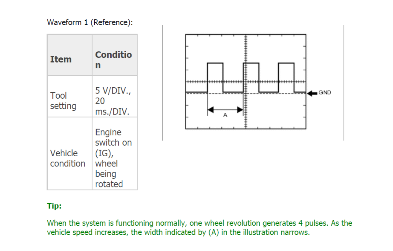
Speed signal (Output) - Pulse generation (Waveform 1 Diagram below)
Speed signal (Input) - Pulse generation (Waveform 1 Diagram below)
I've attached the waveform diagram below. Can anyone tell me if there is a easy and cheap way to emulate this so that I can simulate speed and send this data to the cluster? I'm not sure what the difference between input and output on the cluster pins are either.


