Maker Pro
Maker Pro

Amplitude Modulation using Op Amp.

CDRIVE

Hauling 10' pipe on a Trek Shift3
I have never get a real AM signal. I have built circuits which just add the carrier and the modulating waves, and althought the resulting wave has the modulating wave in both edges (in phase instead of counterphase as in real AM), I don't know why this kind of solution is not used in radio.

Perhaps, because it's not really AM. ;)
 
I'm agree, but my doubt still remains. During simulations, I've been able to extract the modulating signal from that kind of "added waves", using the same detector used for true AM. (The one present in the VEF206 radio)
 
This is what I'm talking about. The modulating signal is there and can be extracted using a simple diode. What is the reason why this method is not used?
 

Attachments

  • Added waves (1kHz + 100kHz).JPG
    Added waves (1kHz + 100kHz).JPG
    43.9 KB · Views: 515
Miguel, I suspect that there might be something wrong with your software. In the schematic you showed it uses an op amp as a veravle gain amplifier. The gain is modulated by your audio coming into the gate of the fet. So the fet is simply being used as a variable resistor. I've done this many times with very good results. The trick is that you keep the level to just a few millivolts on the drain. It could be that your sofwere will not simulate a fet in this mode. You might have to build up the circuit and see what happens.
 
Well, this is what I finally get. I used 1V of negative bias at the gate of the JFET.
 

Attachments

  • Op-Amp and JFET.JPG
    Op-Amp and JFET.JPG
    103.7 KB · Views: 2,839
This is what I'm talking about. The modulating signal is there and can be extracted using a simple diode. What is the reason why this method is not used?

The diagram you show (#23) is just the addition of the radio frequency signal and the audio signal. If this is sent through a transmitter, the audio signal will not be sent and the result will be a constant amplitude carrier.

You can make a modulator with a switching transistor for the radio frequency with its collector voltage derived from the audio frequency, this is series modulation.
You can also use shunt modulation with a transistor to divert some of the power to the switching transistor.
Note that the output will not be a sine wave because it contains many frequencies and so it will need a filter to select the frequency you want.
 
Last edited:
duke37 said:
the audio signal will not be sent and the result will be a constant amplitude carrier.
Please be patient with me and forgive my insistence regarding this, but why not. Some kind of filtering effect in the antenna?
 
This is where mathematics comes into it.
Modulation involves multiplying two sine waves.
Sin(A) * sin(B) = sin(A+B) + sin(A-B)
In othe words sidebands will be produced above and below the carrier.For normal AM, the carrier is transmitted along with the sidebands. The original low audio frequency will not get through the transmitter which will be tuned around the carrier frequency.
Modern ham transmitters use single sideband where the audio frequency is balanced out and the carrier also, one sideband only is then selected. This gives a low bandwidth and the transmitter only gives an output when there is information to be transmitted, alowing higher peak powers.

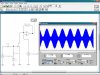
If you do a Fourier analysis of the signal in #25 you will see that you have a carier with two sidebands.
 

(*steve*)

¡sǝpodᴉʇuɐ ǝɥʇ ɹɐǝɥd
Moderator
Well, this is what I finally get. I used 1V of negative bias at the gate of the JFET.

And that's beautiful!

Next trick is to see if it works as well with real world components.

The bandwidth of the op-amp may be an issue.
 
Thank you very much for the explanation, duke. I'm gonna try to do the Fourier analisis to both kind of signals.

Steve said:
Next trick is to see if it works as well with real world components.
I intend to mount a simple circuit in a protoboard to see what happen. I will use the FET that you sent me mounted on a little PCB.

Yes, I know Op-Amps are limited in bandwidth, I will reduce the gain in order to keep the gain/bandwidth product as favorable as possible. If necessary I will use a transistor to amplify the Op-Amp output.
 

CDRIVE

Hauling 10' pipe on a Trek Shift3
Thank you very much for the explanation, duke. I'm gonna try to do the Fourier analisis to both kind of signals.

Miguel, nothing wrong with doing a Fourier Analysis but here's a simpler demo of what I call pseudo AM, using the wavefrom you described. Look what happens when the modulated signal is coupled through a 1000pF cap. As you can clearly see there's no perceptible audio energy coupled to RL. If you study the modulated RF plot you can see that the actual RF level doesn't change at all, just the base line. Yes, there will be some detectable audio but it will be feeble.

Chris
 

Attachments

  • PseudoAM.JPG
    PseudoAM.JPG
    54.3 KB · Views: 314
Last edited:
Now I got it. Thanks.

This is what I got passing true AM signal throught the same RC filter (1nF, 50ohm)

Blue trace: Signal before the filter.
Red trace: Signal after the filter.

It can be seen that audio signal has the same ratio (+/-) relative to the carrier in both cases.

Anyway, I found that i don't know how to use the Bode plotter of this software. :mad:
 

Attachments

  • True AM.JPG
    True AM.JPG
    57.9 KB · Views: 470
Last edited:

CDRIVE

Hauling 10' pipe on a Trek Shift3
My spice is Tina. There's quite a few functions I haven't learned to use yet.

Chris
 
Top