Maker Pro
Maker Pro

2 finger ECG circuit

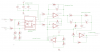
Hello everyone. I am currently doing a personal ECG project. I would like to design a two electrode portable ECG that I can bring around. I followed this circuit from cs.washington.edu (credits to them) .Circuit .pngI have attached the photo with this post. I am unable to get any ECG wave from the circuit. I hooked up the circuit to an Arduino uno and adafruit tft board. The arduino and lcd work fine. I do not understand how the circuit functions and what mistake am I making. please help. Thank you in advance.
 
Look at my reply in the other forum about the common mode cancellation signal that is missing in your circuit and where the three probes should be connected on the patient.

If you want to measure heartbeats on a finger then use an IR LED and IR detector that "sees" blood flow pulses.
 
Look at my reply in the other forum about the common mode cancellation signal that is missing in your circuit and where the three probes should be connected on the patient.

If you want to measure heartbeats on a finger then use an IR LED and IR detector that "sees" blood flow pulses.

Hi Audioguru I really appreciate the quick reply! Yes, I am aware of having three probes to measure ECG. It will give a better reading. I came across this product called Alivecor ( https://www.alivecor.com ). I was intrigued by it and so I was interested in building a two finger ECG. This is the completed circuit the talented people from cs.washington.edu came up with. They were able to get the trace from their input. The resulting oscilloscope is reading is here too. I have attached the photos with this thread. Once I get back from work I can post my completed circuit and the oscilloscope reading.

I am not sure what mistake I am making. All the connections were fine. Maybe my body signal is too weak. Is there any way on how I can improve on this circuit to get a better ECG. Thank you!
 
You never posted the schematic from cs.washington.edu. Maybe the schematic you posted is theirs or is it your copy? The bandpass filter is not bandpass, instead it is lowpass.
 
You never posted the schematic from cs.washington.edu. Maybe the schematic you posted is theirs or is it your copy? The bandpass filter is not bandpass, instead it is lowpass.

Oh I am really sorry for the confusion. This is the completed circuit and schematic from cs.washington.edu. They were able to get the trace from their input. The resulting oscilloscope is reading is here too. It is so intriguing I replicated the exact same schematic. Hey, thank you for the bandpass tip! Once I get back I will check it out! thank you for the quick reply.
 

Attachments

  • AFE-wiring.jpg
    AFE-wiring.jpg
    64.7 KB · Views: 213
  • AFE-trace.jpg
    AFE-trace.jpg
    62.8 KB · Views: 238
  • Circuit .png
    Circuit .png
    128.6 KB · Views: 233
The datasheet for the INA128 says that its minimum supply is 4.5V but you have only 3.3V so no wonder it does not work.
 
Top