Maker Pro
Maker Pro

Zeroing out a LM317 reference voltage with a zener - PSU build

hevans1944

Hop - AC8NS
... For learning ,
the way to go is building the linear P.S using only transistors,diodes and op. amps ,
no 3 pins regulator ICs at all.;)
Ha! If going to that extreme, build the op-amps, too, using discrete transistors and resistors and perhaps a few capacitors. And diodes! Loved your post on the XL741 @chopnhack!

You can learn a lot about 3-terminal regulators by actually using them and discover that adding an op-amp or two or three plus some high-current transistors will really soup things up. Hot rod power supplies if you will (you don't know what I got). But for NOW all we need is a basic bench power supply capable of powering up a few prototype circuits without requiring a second mortgage on the house or pledging a child to a lifetime of indentured servitude.
 
Last edited:
Not to that extreme...
Yes you can learn a lot about regulators ....from there smoke-sines as well;)

But seriously ,
I think building a simple single-output low-current regulated P.S with current-limit is essential for learning.
Using only the classic series pass transistor with a transistor as an "error-amp" + ref. zener-diode.and a current sensing resistor. not very complicated but very educational.

And on the issue of real-estate:
Use any "small" available cheap transformer(the most expansive part in a linear P.S),one from the scrapyard will do fine.

BTW:
Turns out this forum is a bonus English class for me...
I do need to "open a dictionary" to understand some of the words you are using ;)
 

hevans1944

Hop - AC8NS
A challenge, dead bug or professional pcb?
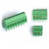
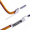
Since you have already demonstrated the capability to have PC boards manufactured on a previous thread, I would go the professional PCB route. But do a prototype first. Do what you did before and upload schematics and board layouts for our inspection, criticism, and inspection. A few iterations should get you to the point where you can confidently order one or more boards. You may be able to get by with a single board design, depending on circuit complexity and bells and whistles you end up including in the design. From a maintenance view, separate boards for each power supply output would be easiest to troubleshoot and repair. Pay attention to how you get power in and out of the board(s). I like those screw-terminal blocks that you can solder directly to the board and use ferrules soldered or crimped onto the ends of the stranded wires.

upload_2016-4-24_23-37-10.jpeg
images
upload_2016-4-24_23-41-22.jpeg

The ferrules work best with a "star" crimping tool, but these are a little pricey. Soldering works okay, especially if you invest in Teflon insulated wire so the heat doesn't cause the insulation to contract back up the wire. I like the ones in the last image above that allow you to label the wires, but that isn't necessary. You can print wire labels and wrap them around the wire under some clear shrink tubing for a professional appearance. Back in the day, we had a device that actually printed text right on the insulation (because the government contract required it) but I have never seen a way to do that for hobby purposes.
 

hevans1944

Hop - AC8NS
Would something like this work as a star crimper? Its reasonably priced.
I think it would work. The one I used was several hundred dollars and was made for crimping wires to pins inserted in a high-density circular bulkhead connector. I re-purposed it to crimp ferrules, but the tool you found is not only inexpensive it also appears to be designed to crimp wire ferrules! Maybe I will buy one too, now that I know it won't break the bank. Good find!
 
No plan as of yet, but I did score a nice find via recycling my UPS today - heavy duty power cord with strain relief! So that kind of counts as working towards this goal ;-)

Sorry for the picture - the strain relief is the type where you notch your case and slip the molded relief area into the notch. If its loose, I can shim it with some washers and epoxy it in place. The iron core had me curious, should I keep it or just unwrap the wires and set aside for another day?

Btw - the board is just chock full of parts that might be useful. Lots of x rated caps, some relays and a bunch of transformers that are not coming up in a google search. I spotted 4 IRF3205 fets - they are attached to the huge chunks of aluminum on the left. There are about 9 more fets of some kind with heatsinks as well.

20160503_183446_zpsyyzpimqy.jpg
 

hevans1944

Hop - AC8NS
That is a good find. But it looks pristine! Are you sure it is not repairable? Sometimes the only thing that fails in a UPS is the gel-cell battery pack.
 
... fails in a UPS is the gel-cell battery pack.

Agreed, I've had this unit for about 8 years. I've replaced the battery twice and still don't get the appropriate run time as well as periodic shut offs, I figured that the circuitry may have fallen out of spec. I assumed these units take a beating with load regulation and surge protection, so I just replaced it to be safe. I was about to bin it and realized - hey, that's a great cord! After the cord, I found a bunch of mosfets inside - which I probably destroyed a few - was desoldering the heat sinks and managed to short the source of the fet with the heatsink via the solder wick - saw a spark :-( I did lift off several monolithic aluminum heatsinks for to-220 packages, some of those x rated caps and a relay. Solder sucker works pretty good!

So about that iron doohickey at the end of the power cord - I guess its there to have an effect on the magnetic field, but it doesnt make much sense to me since both line and neutral are wrapped around the iron core. What's it purpose? Why not wrap only the line side?
 

hevans1944

Hop - AC8NS
It's called a "common mode" choke. It suppresses switching transients from inside the UPS getting back out on the power line.. either hot or neutral. We use them in amateur radio coaxial transmission lines to suppress "common mode" currents that travel back on the outside of the coaxial cable braid and create "arcs and sparks" back in the shack. Problem usually only occurs at higher power levels, but it is always a good idea to suppress common mode currents. Many hams suppress common mode RF without using the ferrite cores by simply making a few loops of out of the coax where it attaches to the antenna, holding the loops together with black tie-wraps or even electrical tape. Four or five turns on a eight or ten inch diameter provides enough inductance to suppress amateur radio RF from propagating back down on the outside of the coax. If that isn't enough, they feed the coax through ferrite cores. Some hams can get pretty carried away with this, placing a dozen or more cores on the coaxial cable in an attempt to keep RF out of the shack.

At the switching frequencies of your UPS (several kilohertz most likely) it requires more inductance to get the same effect, hence the powdered iron cores to wrap the wire around. Sounds like you have unearthed a real treasure chest thar, matey!
 
It's called a "common mode" choke. It suppresses switching transients from inside the UPS getting back out on the power line.. either hot or neutral.
In that case I will keep it on there - I doubt I will have large loads, but I haven't spec'ed out a cap for the psu yet, and that cap can very well produce a large transient! Thanks for the explanation - I was going to say choke, but I didn't understand just what it was attenuating!
Sounds like you have unearthed a real treasure chest thar, matey!
The cord alone is treasure, the rest is extra booty. :D If any of those fets survived it will be a miracle!! LOL We shall see.
 
Top