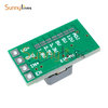
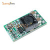
A zener diode circuit such as yours will provide a rather coarsely stabilized output voltage only at the cost of wasted energy (power dissipation in the resistor and diode). It is no more complex to use a 3 pin fixed volage regulator like an 7805 as suggested by Ylli. If you really stive for energy efficiency, there are swithc mode pluf-in replacements for the 7805 with low power dissipation.
Ideally isolated supplies would minimize interference. However, this means having two power supplies bringing additional cost and space with them. Your can work with a single supply but you have to use good wiring and decoupling:
- Keep the ground of the arduino and the motor on separate wires that meet at the power source's negative output only. THis way the motor current wil influence the arduino the least.
- Kepp the +12 V lines to the motor and to the arduino also separate, meeting at the powrr source's positive output.
- It is also a good idea to use twisted wires for the connection from power supply to motor and 5 V regulator. Twisted wires will minimize magnetic coupling of noise.
- In addition you may want to add a simple lC filter in the motor's positive supply. You can get these e.g. from RC hobbyist suppliers. Add the filter as close to the motor as possible.
- Do not forget to apply the filter capacitors to the 5 V regulator's input and output as recommended by the IC datasheet. Also place the regulator as close to the arduino as possible.


