Hi
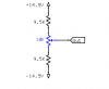
Is it possible to wire a pot as a voltage divider so that it gives 0v DC at its mid point of resistance, and positive voltage one way, and negative the other?
I have an input to a synthesiser that takes -5vDC to +5vDC and i would like to build a simple control for it.
Is it possible to wire a pot as a voltage divider so that it gives 0v DC at its mid point of resistance, and positive voltage one way, and negative the other?
I have an input to a synthesiser that takes -5vDC to +5vDC and i would like to build a simple control for it.
")