Sir joseph Jerome E. Sanchez . . . .
A CONTINUANCE . . . .
Reference to post #11 and its 2nd photo down where we see that the male connector from the sensor plug mates with the female connector that goes down to the control electronics.
With that plug in process, there is being a retaining of the RED and BLUE wires color coding, but a transition of the sensors YELLOW which changes to a WHITE wire code and the sensors GREEN, which changes to a BLACK wire code.
So down at the control board we will be interested in those BLACK and WHITE wire connections, to see if they get directly connected together by the PCB foil path circuitry.
Actually . . . . just after you sent the supplemental photos of the main controller board and with my having been able to trace out the path of the input sensor related circuitry, which pointed out BLUE as being the SENSOR output related
wire.
Plus the YELLOW and GREEN wires are being joined together right at the sensor board foil path ground plane .
NEW REFERENCE MARK-UP PHOTO . . . . .
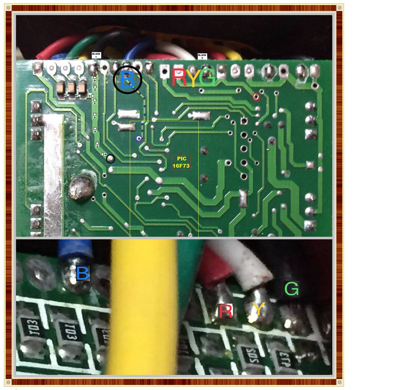
RE-REFERENCE . . . . SENSOR BOARD PHOTO . . . . .

To recount . . . .See top photo above . . .with your labelling of the B and its BLUE wire which takes a path down the BLUE dots until the final BLUE circle which is a thru the board feed thru plated hole, which lets the foil path continue on the other side of the board and its end at an input port of the PIC16F73 u-processor of the micro controller board.
BLUE wire is now accounted for.
Looking at your Y AND G mark ons for the pads of the now transposed Y to WHITE wire and the G to BLACK wire.
I don't believe that your superimposed lettering is hiding any foil interconnect between the Y G pads.
Looking at the lower photo, one cannot make out, if there is being a Y-G pad interconnect there also.
So that positively confirms nothing visually.
Next look at the R label RED wire and see that it ties into a WIDE foil path going downwards, then to the right and up to another pad which connects to another RED wire on top.
The path continues further to the right and then drops down and ends at a RED circle, to pass thru a plated hole to the other side of the board, to continue.
This just further confirms the RED wire as being the color code of wiring used for the + power connectivity of the unit.
Plus RED is a being a COMMON wire color coding for + power.
We were looking for the ground / negative connection for the units wiring and back at the plug we transitioned from a GREEN . . an also sometimes ground wiring code . . . to a BLACK wire which is being a definite negative wire connection used in electronics wiring color coding.
(Exclude the AC ELECTRICAL POWER wiring boys . . .. . which use BLACK ( the color of DEATH) for the AC HOT wire color coding .)
Seeing that BLACK wire at the BLACK 2 designator and seeing only a single foil tab connection , see that you also have a BLACK 1 marker further to the left.
On that one you can see its BLACK arrow path down and an intermediate tie in to a path to the left that grabs 3 ground connections for three side by side SM block ceramic caps.
The path continues down to the BLACK circle where the path transitions over to the other side of the board.
Do note that this ground /negative is using a WIDE foil path, such as the counterpart + supply is also using.
NOW . . .we know . . .
1 . . . That the RED wire at the sensor board is being the + power wire and is the sole intact wire at the board .
2 . . . We have ascertained by the flow path, that the BLUE wire is being the SENSOR data output wire from the sensor board.
3 . . . We now know that the GREEN wire originating at the sensor board, transitions to a BLACK color coding and connects to controller board negative / ground connection.
4 . . . By sole process of elimination, the remaining WHITE wire at the controller (or YELLOW at the SENSOR board) is also going to get connected to the ground plane at the sensor board.
WIRE RECONNECTIONS . . . . . BIKE BATTERY BEING TOTALLY DISCONNECTED / UNPLUGGED
At the sensor board the intact RED wire, still has its long enough service loop length on it. BUT . . .the other three broken ones look somewhat short, since they will need their ends clipped off flush and about 2-4mm of wire insulation is bared on their ends and tightly twisted and then rosin fluxed and solder tinned. After that, process I feel that they might be too short / as compared to the RED ones length.
So you might as well take a # 11 Exacto knife and peel back enough outer cable covering and clip off shielding mesh to end up with the original length of the RED wire for the other three, now shorties.
One precaution you want to take is to cut the shield mesh frizzies off, as short as you can and put a protective insulative covering over the braid wires ends. I would use a ring around of silicone rubber or E6000 if you have it available.
That keeps the frazzled wire ends of the shield mesh in check, so that they could not press into and short between the 4 wire pads.
After completing the 4 wire connections resoldering , a layer of E6000 over them would give double protection,
The E6000 is QUITE tenacious, but will strip off in clinging pieces, being easier for rework, as being compared to silicone rubber which almost requires EVERY bit scraped off, with the safety of non board damage by use of a wooden stick.
We assigned A-B-C-D wire pads to the SENSOR board and if I am not seeing a crossing of wires on the photo of the sensor board, the RED wire is on top with YELLOW being just beside it and BLUE wire is on bottom with GREEN wire being just beside it.
Soooooooo if you have the wire ends prepped and pass the whole cable thru the hole and loop each wire back to connect to its respective solder pad. That would have pad A still receiving RED wire, while pad B is receiving YELLOW wire, pad C is receiving GREEN wire and pad D is receiving BLUE wire. That results in having no wire twistovers, for the center two.
The A-B-C-D pads show an EPON clear conformal coating over them . . as I suggested recoating them . . .so your soldering iron may fight and stink in initially getting on down to the solder joints proper and the broken off wire shards.
Totally clear the holes using . . . . . solder sucker- /or/-solder wick- /or/- round wooden toothpick- /or/- TAPPA-TAPPA and BLOW.
Go for it ! . . . . . . before your sons convention bicycling develops such largened calf muscles that he is no longer able to get on his pants over his largened legs and has to go Yukata .
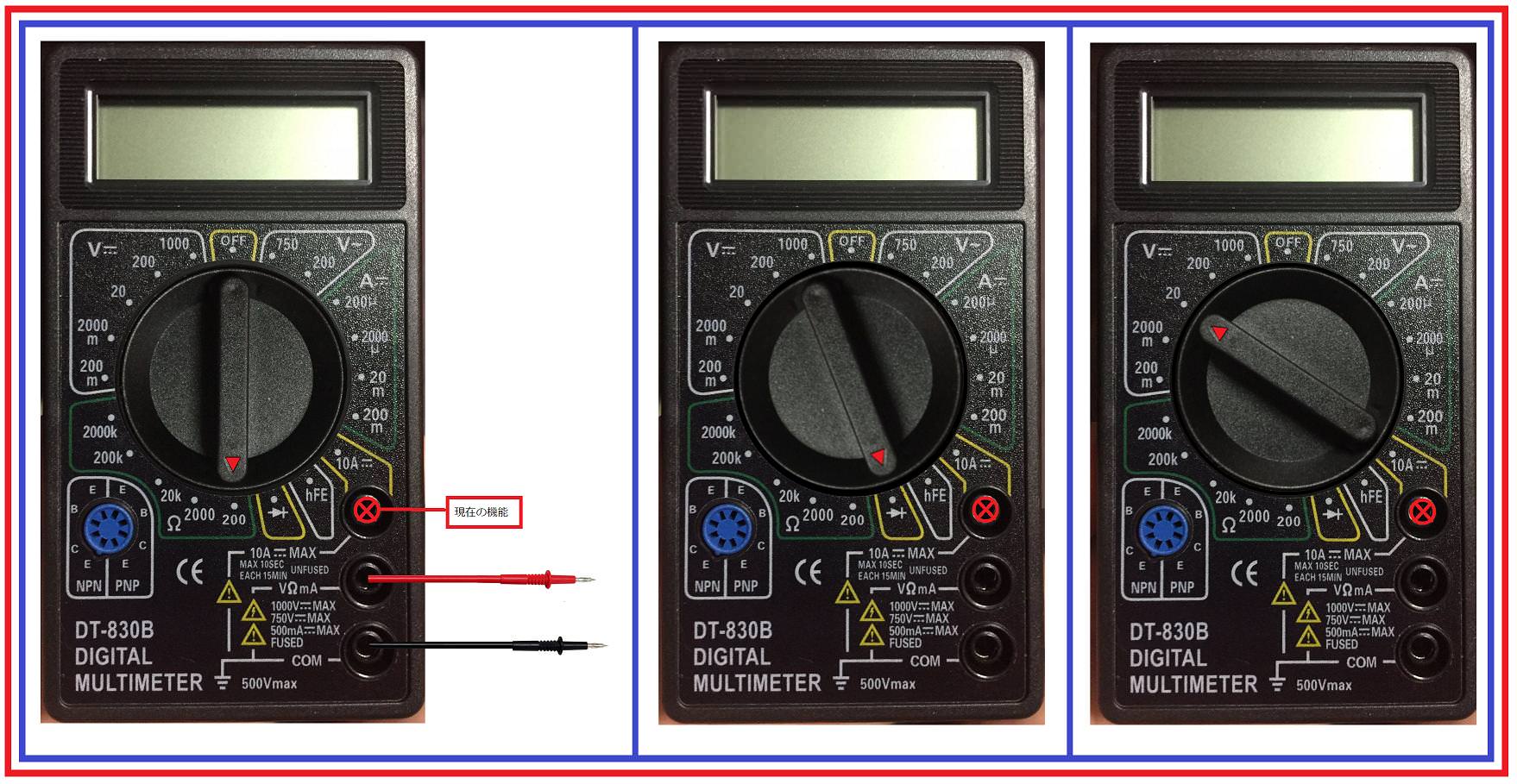
BTW . . . . here is how your meter connection points to probes would be made.
The first metering set up is for its lowest 200 ohms resistance measurements
The second metering set up is for its use as a continuous aural beeeeeeeeeeeeep, for less than ~200 ohm resistance reading. ( But you want near 0 ohms )
The third meter set up is for up to 20 VDC voltage reading. . . . .BTW what is the E-bike battery's voltage rating ?
Mmmmmmmmmmm me gusta a saber . . . con su nombre . . .parece que usted puede a hablar Espanol . . tambien ?
73's de Edd
.....
A CONTINUANCE . . . .
Reference to post #11 and its 2nd photo down where we see that the male connector from the sensor plug mates with the female connector that goes down to the control electronics.
With that plug in process, there is being a retaining of the RED and BLUE wires color coding, but a transition of the sensors YELLOW which changes to a WHITE wire code and the sensors GREEN, which changes to a BLACK wire code.
So down at the control board we will be interested in those BLACK and WHITE wire connections, to see if they get directly connected together by the PCB foil path circuitry.
Actually . . . . just after you sent the supplemental photos of the main controller board and with my having been able to trace out the path of the input sensor related circuitry, which pointed out BLUE as being the SENSOR output related
wire.
Plus the YELLOW and GREEN wires are being joined together right at the sensor board foil path ground plane .
NEW REFERENCE MARK-UP PHOTO . . . . .
RE-REFERENCE . . . . SENSOR BOARD PHOTO . . . . .
To recount . . . .See top photo above . . .with your labelling of the B and its BLUE wire which takes a path down the BLUE dots until the final BLUE circle which is a thru the board feed thru plated hole, which lets the foil path continue on the other side of the board and its end at an input port of the PIC16F73 u-processor of the micro controller board.
BLUE wire is now accounted for.
Looking at your Y AND G mark ons for the pads of the now transposed Y to WHITE wire and the G to BLACK wire.
I don't believe that your superimposed lettering is hiding any foil interconnect between the Y G pads.
Looking at the lower photo, one cannot make out, if there is being a Y-G pad interconnect there also.
So that positively confirms nothing visually.
Next look at the R label RED wire and see that it ties into a WIDE foil path going downwards, then to the right and up to another pad which connects to another RED wire on top.
The path continues further to the right and then drops down and ends at a RED circle, to pass thru a plated hole to the other side of the board, to continue.
This just further confirms the RED wire as being the color code of wiring used for the + power connectivity of the unit.
Plus RED is a being a COMMON wire color coding for + power.
We were looking for the ground / negative connection for the units wiring and back at the plug we transitioned from a GREEN . . an also sometimes ground wiring code . . . to a BLACK wire which is being a definite negative wire connection used in electronics wiring color coding.
(Exclude the AC ELECTRICAL POWER wiring boys . . .. . which use BLACK ( the color of DEATH) for the AC HOT wire color coding .)
Seeing that BLACK wire at the BLACK 2 designator and seeing only a single foil tab connection , see that you also have a BLACK 1 marker further to the left.
On that one you can see its BLACK arrow path down and an intermediate tie in to a path to the left that grabs 3 ground connections for three side by side SM block ceramic caps.
The path continues down to the BLACK circle where the path transitions over to the other side of the board.
Do note that this ground /negative is using a WIDE foil path, such as the counterpart + supply is also using.
NOW . . .we know . . .
1 . . . That the RED wire at the sensor board is being the + power wire and is the sole intact wire at the board .
2 . . . We have ascertained by the flow path, that the BLUE wire is being the SENSOR data output wire from the sensor board.
3 . . . We now know that the GREEN wire originating at the sensor board, transitions to a BLACK color coding and connects to controller board negative / ground connection.
4 . . . By sole process of elimination, the remaining WHITE wire at the controller (or YELLOW at the SENSOR board) is also going to get connected to the ground plane at the sensor board.
WIRE RECONNECTIONS . . . . . BIKE BATTERY BEING TOTALLY DISCONNECTED / UNPLUGGED
At the sensor board the intact RED wire, still has its long enough service loop length on it. BUT . . .the other three broken ones look somewhat short, since they will need their ends clipped off flush and about 2-4mm of wire insulation is bared on their ends and tightly twisted and then rosin fluxed and solder tinned. After that, process I feel that they might be too short / as compared to the RED ones length.
So you might as well take a # 11 Exacto knife and peel back enough outer cable covering and clip off shielding mesh to end up with the original length of the RED wire for the other three, now shorties.
One precaution you want to take is to cut the shield mesh frizzies off, as short as you can and put a protective insulative covering over the braid wires ends. I would use a ring around of silicone rubber or E6000 if you have it available.
That keeps the frazzled wire ends of the shield mesh in check, so that they could not press into and short between the 4 wire pads.
After completing the 4 wire connections resoldering , a layer of E6000 over them would give double protection,
The E6000 is QUITE tenacious, but will strip off in clinging pieces, being easier for rework, as being compared to silicone rubber which almost requires EVERY bit scraped off, with the safety of non board damage by use of a wooden stick.
We assigned A-B-C-D wire pads to the SENSOR board and if I am not seeing a crossing of wires on the photo of the sensor board, the RED wire is on top with YELLOW being just beside it and BLUE wire is on bottom with GREEN wire being just beside it.
Soooooooo if you have the wire ends prepped and pass the whole cable thru the hole and loop each wire back to connect to its respective solder pad. That would have pad A still receiving RED wire, while pad B is receiving YELLOW wire, pad C is receiving GREEN wire and pad D is receiving BLUE wire. That results in having no wire twistovers, for the center two.
The A-B-C-D pads show an EPON clear conformal coating over them . . as I suggested recoating them . . .so your soldering iron may fight and stink in initially getting on down to the solder joints proper and the broken off wire shards.
Totally clear the holes using . . . . . solder sucker- /or/-solder wick- /or/- round wooden toothpick- /or/- TAPPA-TAPPA and BLOW.
Go for it ! . . . . . . before your sons convention bicycling develops such largened calf muscles that he is no longer able to get on his pants over his largened legs and has to go Yukata .
BTW . . . . here is how your meter connection points to probes would be made.
The first metering set up is for its lowest 200 ohms resistance measurements
The second metering set up is for its use as a continuous aural beeeeeeeeeeeeep, for less than ~200 ohm resistance reading. ( But you want near 0 ohms )
The third meter set up is for up to 20 VDC voltage reading. . . . .BTW what is the E-bike battery's voltage rating ?
Mmmmmmmmmmm me gusta a saber . . . con su nombre . . .parece que usted puede a hablar Espanol . . tambien ?
73's de Edd
.....
Last edited:

