Maker Pro
Maker Pro

Why use diodes in this circuit

I am hoping someone can help. It might be kind of a dumb question but in the circuit diagram below, what is the point of having the circuit feedback on itself through the diode?
pnp-switch-motor_3.png
 
The diode is to suppress the negative inductive spike from the motor when the switch is opened, to prevent damage to the transistor or switch.

Incidentally the transistor circuit won't work as shown with the posted control voltages.
The OFF voltage must be equal to the supply voltage (12V here) so that the base-emitter voltage is near zero and no base-emitter current flows.
 
We are guessing that M1 is an inductive motor.
Hee, hee. Use one hand replacing the diode then tell us high high you jump when the transistor turns off.
 

Harald Kapp

Moderator
Moderator
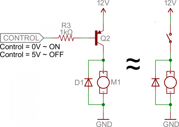
Apart from the diode part, which has been explained correctly, the circuit shown in post #1 has a design flaw and will not work correctly:
With a control voltage of 5 V the motor should be off. But with +5 V on the control input, transistor Q2's base is still negative with respect to the emitter (+12 V). Thus Q2 will be on. Base current will be ~Ib = (12 V -5 V -0.6 V)/1 kΩ = 6.4 mA.
With a current gain of e.g. 50 this will be good for up to ~ 300 mA drive current for the motor. SO the motor will be on, not off.

Solutions:
  1. Use a NPN transistor and switch GND, see e.g. here.
  2. Use a level shifter (see e.g. this example which is for 5 V but can easily be modified for 12 V).
  3. Use a 12 V control voltage.
 
Top