I often use a
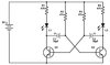
Vector pad cutter, a hand tool that creates a small circular island, or pad, surrounded by an annular ring of removed copper on an copper-clad bare board after you drill a pilot hole for the pad. Components are mounted through the hole in the pad and soldered in place, just as you would on a Veroboard or a printed circuit board. The tool is also available without a handle, which is handy if you have a drill press or CNC arbor plus carbide drills and need to make more than a few dozen pads. For "Manhattan" style construction (popular in prototype RF work) hollow, diamond-edged, circular cutters in various diameters for use in a drill press are available from
this company.
Some folks use a CNC router to make isolated traces on bare copper boards, but that can take a long time for moderately complicated circuits. Bare copper-clad boards are readily available for making printed circuit boards as
@BobK mentioned, so many electronics hobbyists may have a few pieces laying around. It's a personal decision by the hobbyist whether to use point-to-point wiring or to make a PCB.
Circuit construction using donut pads you make on bare copper-clad board is similar to using Veroboard except you provide your own wires to connect components, sometimes using the component leads for this purpose if they are long enough. My favorite connection method is ordinary 24 AWG tinned buss wire, with a Teflon insulating sleeve cut from a roll of same to whatever length is needed... remember, bare copper-clad board will short out connections that aren't insulated from the board! But that bare board also makes an excellent ground plane too. And the other side can often be used as a power plane if it is copper-clad too.
I also sometimes use 30 AWG wire-wrap wire to make connections, but that requires a good stripping tool, and stripping the wire slows things down. Who isn't in a hurry to see if their project will work, especially after confirming that a solderless breadboard rendition is satisfactory? Wire-wrap wire is especially good for wiring DIP (Dual In-line Package) sockets that have short solder-tails for PCB mounting instead of having wire-wrap posts.
If you are using expensive ICs that come in round cans with tiny gold-plated leads, it makes sense to invest a few bux for sockets to mount them... those sockets need either a PCB or 30 AWG wire-wrap wire to connect to the rest of your circuitry. I will admit it has been a few years since I've had to do this, but I discovered one of those shiny round cans with the tiny wire leads in my junque collection the other day. It's obsolete of course, and a replacement is probably only obtainable at a huge cost from one those companies that buy up the last production run of a part and hold on to it for years, decades even, so they can reap a huge profit from anyone who really, really, needs one. But it might be fun to play with the one I happen to have, just to recall how we did it "back in the day."
")