Maker Pro
Maker Pro

why is this comparator triggering on falling edge?

Hi,

So this basic comparator below...

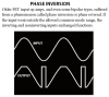
As pictured it works fine. the function generator pumps in a 10vp-p square
and everytime it goes high the RC pulse triggers a positive output pulse (at pin 1)

the diode keeps the input at ground whenever the function generator is negative. Thats fine

BUT why does the comparator produce a positive pulse on the negative input swing when I take the diode away?

The RC pulse at the input is negative and so A(V+-V-) should also be negative!!!

yet with no diode here I get a positive pulse at pin 1 every time the square wave switches.

its realy bugging me, any ideas?


falling comparator.PNG
 
A common characteristic of many opamps, particularly older designs, is that when you overdrive the input below the negative operating voltage pin, the output inverts. Later chips have added circuitry internally to prevent this condition. Sonmthing in the input stage gets reverse biased and shuts down, sending the wrong voltage to the next stage (usually the voltage amplifier). Form there on, the rest of the chip just deals with the signal it is given.

ak
Thanks. thats very useful info. Ive never heard of that. do you have any good references that explain it properly?
 

(*steve*)

¡sǝpodᴉʇuɐ ǝɥʇ ɹɐǝɥd
Moderator
One important reference is the datasheet. It will give you limits on input voltage ranges. If your circuit exceeds these, you should only be surprised if it continues to work correctly.
 
One important reference is the datasheet. It will give you limits on input voltage ranges. If your circuit exceeds these, you should only be surprised if it continues to work correctly.
yes im looking at the datasheet but they can be a bit confusing at times. This is what it says

"Differential Input Voltage Range Equal to the Power Supply Voltage"

so does this mean that if powered by +/-6v the term (V+ - V-) can be 12V or less?

also theres no mention of it inverting when overdriven
 

(*steve*)

¡sǝpodᴉʇuɐ ǝɥʇ ɹɐǝɥd
Moderator
You also need to look at the maximum range of input voltage on the input pins.

For example I bet it has limits on how far outside the supply rails they can be.
 
ive tested it in multisim with a smaller input and it doesnt invert.

thats interesting. I guess my negative pulse was over the limit by a few volts. so this kinda makes sense. Thanks
 
You also need to look at the maximum range of input voltage on the input pins.

For example I bet it has limits on how far outside the supply rails they can be.
well for my LM324 in the maximum ratings section. all I can see that looks appropriate is

"Input voltage - MAX = 32V"

Is that what your talking about?

given that the maximum voltage used to power the thing in single supply mode is also 32V would it be safe to assume that what it realy means is "Input voltage = Vs" ?

and when they are using all terminology based on single supply mode (e.g 32V and 0V) how would I convert the figures into dual supply mode (e.g +16V and -16V)

in this case would the term "input voltage - MAX" actually be 16V?

sorry but these are the kind of headaches datasheets give me
 

(*steve*)

¡sǝpodᴉʇuɐ ǝɥʇ ɹɐǝɥd
Moderator
I'm assuming this is some sort of homework, so I'm not giving you the answer.

You have a scope connected to the non-inverting input. What does that indicate the range of input voltages is? How does it change when the diode is added or removed?

In the datasheet, when they refer to 0V and 32V, they are referring to the lowest potential as 0V and the highest potential as 32V. What are the highest and lowest potentials of your supply voltage? Remember that voltages are relative, the op-amp doesn't know or care what potential you choose to call 0V.

Post a link to the datasheet you're using (or the datasheet itself) and I can be more specific about what section you need to look at.

EDIT: Hang on a sec, the input is not connected quite the way I thought it was... The answer may be pretty much the same, but the cause is not quite so obvious.
 
I'm assuming this is some sort of homework, so I'm not giving you the answer.

You have a scope connected to the non-inverting input. What does that indicate the range of input voltages is? How does it change when the diode is added or removed?

In the datasheet, when they refer to 0V and 32V, they are referring to the lowest potential as 0V and the highest potential as 32V. What are the highest and lowest potentials of your supply voltage? Remember that voltages are relative, the op-amp doesn't know or care what potential you choose to call 0V.

Post a link to the datasheet you're using (or the datasheet itself) and I can be more specific about what section you need to look at.
ok chrome-extension://oemmndcbldboiebfnladdacbdfmadadm/http://www.ti.com/lit/ds/symlink/lm2902-n.pdf

ps its not homework as such. I have made a very big circuit and am going back over it trying to remember why I did certain things. I often just try stuff and if it works I leave it, but its nice to know why it worked
 
The datasheet for the TL08x and TL07x opamps says that the input common mode voltage range is -12V to +15V when the supply is +15V and -15V (so the inputs do not work properly when within 3V from the negative supply). They do not say that then the output suddenly goes positive like this:
 

Attachments

  • opamp phase inversion.PNG
    opamp phase inversion.PNG
    15.3 KB · Views: 48

(*steve*)

¡sǝpodᴉʇuɐ ǝɥʇ ɹɐǝɥd
Moderator
On the first page of the datasheet, look at the schematic. Q1 and Q4 have their collectors grounded (in this case to your most negative rail). The bases are your inputs.

What happens if either input goes below the collector voltage? Consider the diode junction at CB.

Section 6 on page 4 (absolute maximum ratings) if something you need to consider carefully. Look at the minimum input voltage. -0.3V is really important! This is the input being below your most negative rail.

That diode in your schematic prevents the input voltage from falling below your 0V rail by more than a diode drop. That will be way above your negative rail. Removing it also removed anything limiting hire negative the input can be (yeah you have to be able to mentally so from comparing the voltage to the 0V rail as negative to costing the voltage against your most negative rail. You don't want a reasonable and allowable negative voltage as compared against your 0V rail to become so large that it ever becomes negative compared to your most negative rail).

The consequences to your circuit of exceeding the most positive rail are in this case more benign, but should still be avoided.
 

(*steve*)

¡sǝpodᴉʇuɐ ǝɥʇ ɹɐǝɥd
Moderator
They do not say that then the output suddenly goes positive like this:

They also don't say what happens if you exceed other ratings whick define the envelope in which the device is specified to operate. If they did, the device would be specified to operate in the larger envelope.

In theory they could specify the volume of smoke generated during failure modes, and these would no longer be failures, but specified operation. However, then they would have to ensure the device reliably operated in the manner described.
 
The consequences to your circuit of exceeding the most positive rail are in this case more benign, but should still be avoided.

thanks for the tips. will think on it.

now looking at the schematic im wondering why a large positive input above the pos supply allows it to work at all! wouldnt that bias the PNP all wrong?
 
ok so now whats realy bothering me is why Im not damaging the op amp (lm324) when my positive input pulse is 10.4V. It is greater than the positive supply by 4.4V but the circuit has been performing fine for a month with no heating or performance issues.

Any help here would be appreciated.
 

(*steve*)

¡sǝpodᴉʇuɐ ǝɥʇ ɹɐǝɥd
Moderator
When you take the input above the most positive supply rail, one of two things will happen. The worst is that (for this op-amp) that you exceed the base-emitter breakdown voltage of one of the input transistors. Another alternative is that some diode junction between the input and the positive supply rail becomes forward biased.

If it's still working then the chances are that you've not destroyed an input transistor :)

Your input appears to be reasonably high impedance, so accidentally forward biasing junctions that are normally reverse biased is unlikely to cause sufficient current to flow that would damage them.

The breakdown voltage of base-emitter junctions is pretty low (6 to 8 volts is typical), and I have no idea your signal that is 4.4V above the supply voltage is getting to it, but it must be close (unless -- as I've said earlier there is a diode junction from the input to the positive supply rail).

You could try placing a pair of reverse biassed diodes, from the input to each of the supply rails. Often this is combined with a resistor between these diodes and the input. Effectively, one of those diodes is in your original circuit (but to the 0V rail instead of the -ve rail).
 
OK thanks for the help. The whole machine is built and hand wired. the thought of taking it apart to access that point gives me nightmares, so I think ill leave it and bear it in mind next time.
 
Top