Maker Pro
Maker Pro

What power source and resistors are required for the circuit below?

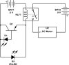
I am trying to build a robot which stops when it detects the edge of a table it's moving on without ic's or a arduino. It consists of a photodiode, when the ir rays emitted from an ir led reflects from the surface to the Photodiode (which is connected in reverse bias from the positive of the battery to the base of a npn transistor) the transistor becomes open, in series with the transistor is a 6v relay coil the relay is used as a switch to on and off the motor this way the motor only spins when the ir is reflected from a surface and will stop when it comes to the edge. The motor requires about 5 or 6 AA batteries in series to work. Currently I can't get it to work. The motor doesn't spin when in the circuit but it spins when I hook it up directly to the battery without the relay. This is because the relay is not switching to close the motor circuit maybe because it's not getting the 6 V it requires. Please help I want to know what batteries to use and the resistors or any other parts required to make it work. Also should I hook up the motor directly in the circuit in series with the transistor or is the relay required and should I connect the Ir led in series with the circuit? Also please suggest if I have to change this circuit in any way.
 

Attachments

  • image.jpg
    image.jpg
    22.6 KB · Views: 111

(*steve*)

¡sǝpodᴉʇuɐ ǝɥʇ ɹɐǝɥd
Moderator
have a look at white line follower circuits to see the sort of thing you'll need.

the circuit you show here is not going to work without a complete redesign.
 
have a look at white line follower circuits to see the sort of thing you'll need.

the circuit you show here is not going to work without a complete redesign.
I looked at this but they require ic or micro controllers to work can you please suggest the edits or link me to a circuit which doesn't use any ic or micro controller.
 

hevans1944

Hop - AC8NS
I am not sure why you are so adamant about not using appropriate technology. Just because you want to do something does not mean you can do it.

It looks like you either do not have enough IR illumination reflected from the table, or the photodiode current does not drive the transistor sufficiently to turn on the relay. You could try using a pair of NPN transistors in the Darlington connection, and place the relay coil in series with the collectors instead of in the emitter circuit. Put a diode across the relay coil, anode to coil, cathode to positive terminal of the battery, to prevent back EMF damage to the transistors when the coil becomes de-energized. You should also use a series current-limiting resistor with the IR LED, placing these two components directly across the 6 V battery. Even all this may still not work if you don't get enough IR illumination into the photodiode, in which case you will need to amplify the photodiode current, typically with an operational amplifier connected as a transimpedance amplifier.

Signal-to-noise ratio can often be a problem when using your approach to edge recognition. Many times a modulated IR source is required to separate the desired illumination (IR LED) from background illumination (reflection of other IR sources from the surface). This means way more complexity than a couple of transistors and a relay is required. So good luck with that.
 
Top