Maker Pro
Maker Pro

Vintage Elka Reverb III

Hi,

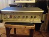
recently I bought the vintage Elka Reverb effect III. Unfortynately there's no documentation on the internet, no schematics, nothing...

I bought it without a pedal that activates the individual sections: REVERB / VIBRATO / FUZZ

By trying different combinations (by connecting the pins in the back socket) I managed to run VIBRATO, FUZZ and BYPASS. But I can not figure out what combination turns on REVERB.

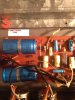
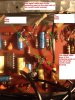
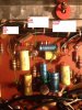
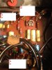
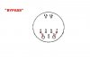
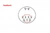
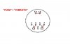
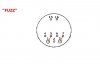
Below you can find photo of "guts" with the description where every PIN is connected on board. I send also photos of combinations of connections, which turns on bypass, vibrato, fuzz and some kind of un-controlled feedback.
Whether on the basis of this information could someone who is the subject of audio write what combination should TURN ON REVERB?

If nothing is connected to the socket, you can hear the reverb, but the signal is sooooo quiet.
With the combination "vibrato" "fuzz" "bypass" the signal is loud (normal) but there is no reverb.
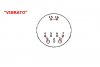
PIN OUT is:
1 - two wires are soldered to this pin. First goes to the TIP of INPUT JACK, the other goes to the board
2 - grounding
3 - to the board,
4 - to the board,
5 - to the board,
6 - grounding
7 - goes to the TIP of OUTPUT JACK,
15 - to the board,
16 - to the board.

Thanks in advance for your help:)
Regards,
Tomek
 

Attachments

  • VIBRATO.JPG
    VIBRATO.JPG
    20.2 KB · Views: 197
  • BYPASS.JPG
    BYPASS.JPG
    20 KB · Views: 238
  • FEEDBACK.JPG
    FEEDBACK.JPG
    20.4 KB · Views: 198
  • FRONT.JPG
    FRONT.JPG
    297 KB · Views: 319
  • FUZZ VIBRATO.JPG
    FUZZ VIBRATO.JPG
    21.3 KB · Views: 156
  • FUZZ.JPG
    FUZZ.JPG
    19.4 KB · Views: 162
  • BOARD.JPG
    BOARD.JPG
    264.3 KB · Views: 227
Last edited:
Did you try Googleing for a schematic?

Thanks for reply! :)

Yup. Tried to find the schematic everywhere. I went through every site that has "elka+reverb+III" in google search. I've reached 19th... No sing of any info...

Even at the company that bought Gem/Lem/Elka company. They replied that there were less than 500 items made.

I also found only one item on Italian "ebay-like" auction site. I've asked this Italian if he could send me photos of interior of the pedal (lucky bas...rd - he has it! :>) so I could build my own. But he didn't answer my question :(
 
Thank you for reply:)
I've checked this site. Unfortunatelly there were no similar schematics there :(

All the best,
Tomasz
 
.

Sir Tomasz . . . . .


By the looks of that unit, with its galvanized sheet metal construction, I can see maybe why there were only 500 units having been made .
As far as the complexity of the circuitry, I am only seeing one integrated circuit and two transistors to the left of your number 4 marker .
Between your number 3 and 4 marker, just below, I am seeing two transistors and what may seem to be a H profile integrated circuit, unless it is being a TO-5 case for a transistor.
Now the question is, on the reverberation aspect, are they using a set of springs or is this being accomplished electronically ?
If this is being done electronically
, I would expect it to be using a Reticon, or a like makers, family of bucket brigade technology to accomplish the reverberation effect.
I would suspect that it might be the far left dual in-line package, as I don't believe I have ever remembered seeing one in a H profile can housing.
Could you please pass us the numbers on the top of the DIP ic on the left and if the other device is NOT being a transistor, pass us the markings on top of it.
As far as your first step in your homework, you see the output jack at the far right-hand, can you identify the tip connection as being connected to one of your already marked connections on the board that you have labeled?
You mentioned, having been able to have a small amount of reverberation to pass through the unit .
Looking at the board I see several yellow polypropylene capacitors used, of which I can make out some of the .1
ufd units, and I suspicion the larger ones to possibly be 1 ufd in value.
What I propose to do is to have you find the wiring connection that is being the same as the tip of the output jack and use a clip lead to connect to it, then use the free end of the clip lead to connect to a 1 µF, from YOUR capacitor spare parts supply, and use the other free end of that capacitor to then
probe through the circuitry to find a stronger reverberation signal.
If we find that stronger signal then we can direct our effort on figuring out, why the loss of the signal between the two points .
I would suspicion this unit to be about a 30 to 40-year-old unit, by noting its technological design curves aspect .
Some newer units use an optical isolator to adjust the coupling of the reverb through the system, wherein a variable voltage varies illumination of a LED within the optical isolator to engage the amount of conduction of
the internal phototransistor of the optical isolator, which is in the feedthrough gain circuit.
Your unit is far behind this technology.
What say you now . . . . on the feedback of those I.c. parts identification, I will be standing by.


73's de Edd


.
 
Last edited:
Dear Sir!
Wow! I must say that I'm very impressed by total professional attitude of yours! :)
I am already totaly gratefull for your reply!

Ok, so first things first:
1. there are at least 8 transistors on the board (see the photos. They are made from the left to the right side of the board)

2. the tip of the output jack is not connected to the board.
It's directly connected to the PIN number "7" in the socket on the back-where one should plug-in the cabel to the pedal.

3. from left to the right the yellow caps are:
.10 / .10 / .10 / .10 / 0.15 / .010 / .022 / .10 / .068 / .047 / .010 / .0010 / .10 / .22

One more time thank you very much for your effort!!!

Kind Regards,
Tomasz
 

Attachments

  • BOARD.jpg
    BOARD.jpg
    240.3 KB · Views: 128
  • 1.JPG
    1.JPG
    279.6 KB · Views: 109
  • 2.JPG
    2.JPG
    302.7 KB · Views: 114
  • 3.JPG
    3.JPG
    272.9 KB · Views: 124
  • 4.JPG
    4.JPG
    239.2 KB · Views: 124
.

Sir Tomasz . . . . .

Thank you . . .Thank you . . .Thank you . . .
for the additional pics.

With those new pictures, I can now see that the "galvanized sheet metal" was being the housing for the units reverb springs.

Seeing better, what I initially thought might have been a round H profile IC, it now turns out to be a TI unijunction 2N2160 transistor, which is being associated with creating the "throb" aspect of the units vibrato effect.

The springs probably are only using 1 -2 transistors to drive them and their picked up signal is probably being processed by that UA739 dual op amp in the14 pin DIP package .

I did not need the YELLOW poly caps values, just noting that one paper or poly 1 ufd cap from YOUR parts supply collection, would be needed for providing a safe degree of D.C. isolation, in order
to trace the signal flow of the reverb signal in troubleshooting..

I will study the pictures for further analysis . . . .as you can see this unit is now confirmed as being circa 70-75' ish vintage.


73's de Edd
 
Last edited:
.


Sir Tomasz . . . . .


That cabling really makes the circuitry hard to see, but for our initial preparation, can you get a shielded line to go to either a guitar amplifier or an amplifier . . . if that is what you're using . . . and one end will plug into the amp the other and will be able to break out of its shielding so that we may solder connect its central wire to a 0 .1 ufd paper / poly capacitor with a short lead at that connection and the other end of the cap is left long enough to probe with.

The specific reverberation portion of this board, is being between where you have your large RED #4 marked , on over to the left as far as the units main filter capacitors.

I suspect the GREEN ( your added mark on) shielded wire is going to drive the Reverb springs from two transistors, of which one deserves a small heatsink on it, that is probably the output driver signal for the springs.

That leaves the RED shielded wire as being the returning feeble reverb output signal, then needing to be amplified.

Initially, can you get an audio test signal going into the main input jack of the unit and then, by using that capacitor, to probe the GREEN connection which, will probably present a pretty strong and clean audio signal.
Then probe the RED line to see if it is strong enough to hear.
If not, try the #1 connection up in the top left corner of the board.
If not we will next have to move down the 739 DIP op amp amplifier, to see if it is passing and amplifying the reverb signal..

Waiting for your progress and comeback before continuing . . .unless you need further procedural info.. . . .or its clarification.


73's de Edd


.
 
Last edited:
Top