Maker Pro
Maker Pro

Variable power supply

I need to make a variable power supply which the out put voltage has to be from 3-15v ,1.5A,
I am going to use the lm317T . I am using the formula V= 1.25x (1+r1/r2)
and as v i placed 15 v . how am i going to make the minmum output voltage as 3v?

Thanks and happy New year
 
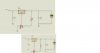
The LM317T needs a potential divider to set the output voltage as you have determined. There are two resistors in this divider, R1 and R2.

The LM317T controls the passes current to get 1.25V between the output and the sense terminal. The easiest way of detrmining the resistors is to decide on a current through the divider. Let us say 1mA, then Rupper will need to be 1.25k.

The rest of the output voltage is across Rlower, in this case, 3V - 1.25V = 1.75V so you will need a resistor of 1.75k to pass 1mA.

Check this with your formula. If the voltage is not critical, go for the nearest preferred values i.e. 1.2k and 1.8k.
 
Tnks for the reply but i still have a question.

So than how can i make the power supply go up to 15v if the resistors selected in the circuit are calculated for 3v .

I know that i have to enter a variable reisistor but my question is how i am going to do the calculations to make it from 3v to 15v
 

(*steve*)

¡sǝpodᴉʇuɐ ǝɥʇ ɹɐǝɥd
Moderator
you make one of the resistors variable (hint - the one with the variable voltage across it).

Check out the datasheet for more information.

Note that your input voltage will need to be at least a couple of volts higher than your output voltage (the specs contain more information), and you will require a hefty heatsink for maximum current at minimum voltage.
 
I know that i have to enter a variable reisistor but my question is how i am going to do the calculations to make it from 3v to 15v

its called algebra. :) 15V = 1.25(1+R2/240) then you solve for R2. R2 = 2640Ohms. Fit a variable resistor larger then 2640Ohms and you will achieve 15V

BTW, you formula was wrong, have another look at the datasheet. It is listed right under the first diagram. Where is says typical applications on the second page. http://www.ti.com/lit/ds/snvs774l/snvs774l.pdf
 
Last edited:
Tnks for telling me that i need to use algebra.

I worked with that formula and I obtained 15v but when i varry the pot it does not go down to 3v .
do you think i have to place a zener diode some were or i did a mistake some were ?

Sry for the bad quality max volt is 15v and the minimum is 1.64


Tnks
 

Attachments

  • Untitled.png
    Untitled.png
    49.4 KB · Views: 174
Last edited:
Well if it went to 1.64V then it surely will output 3V. If you don't want it to go below 3V, then use a regular resistor to give you the 3V min and then in series add a pot to get your max V. When the pot is at 0Ohms, then 3V will be the min.
 
R2 the lower resistor can be made up of a fixed resistor to limit the lower voltage in series with a variable resistor to control the output voltage. The potentiometer should have one end and slider connected to ground and the other end connected to R1 and the reference input.

With R1 = 240 ohms = 1.25V, then 10 times this value on R2 will give 12.5 + 1.25 out = 13.75V.
 
Top