Hi guys
I'm building a Power Supply that has 3 outputs:
0-12V, 0.5A max
-12-0V, 0.5A max
fixed 5V, 0-1A
I'm having problems with the current limited part of the circuit.
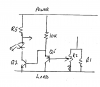
I was simulating the circuit here:
http://freecircuitdiagram.com/2008/08/27/variable-adjustable-current-limiter-circuit/
but I was unable to get it to go down to 0A.
Also, I need to light up a led diode when the current limiter is working, and I can't get how to do that.
Could you give me a hand on this, please?
Many thanks!
I'm building a Power Supply that has 3 outputs:
0-12V, 0.5A max
-12-0V, 0.5A max
fixed 5V, 0-1A
I'm having problems with the current limited part of the circuit.
I was simulating the circuit here:
http://freecircuitdiagram.com/2008/08/27/variable-adjustable-current-limiter-circuit/
but I was unable to get it to go down to 0A.
Also, I need to light up a led diode when the current limiter is working, and I can't get how to do that.
Could you give me a hand on this, please?
Many thanks!