Maker Pro
Maker Pro

using Diodes/NC switches as Motor Limit switches.

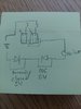
I need some help with a deltadrive 24VDC actuator. The actuator is set up with a Normally Closed switch on either end. When the actuator is at the end of its travel, it pushes a switch to open it. Now instead of a closed switch there is a diode which only allows the motor to reverse till its off the switch.

This setup is on both ends of the actuator. I got the actuator after somebody had taken it apart. Wires were disconnected inside. I cannot figure out how to make it work properly. Would somebody be able to point out what's going on here.

After a bunch of tinkering, here's what I have come up with. If I connect the diodes/switches in series with the motor as drawn in the sketch below I can get actuator to forward and reverse with the switches in the hand unit. ONE of the limit switches will work as I expect it to. With the NC switch opened, the actuator will only work in reverse. Limit switch works as expected. In reverse I hear relay click and motor moves. Forward button clicks relay no actuator movement.

When I hit the other limit switch, neither direction works.

To simplify my troubleshooting, I took the switches out of the pictures and added just a diode. (same as in the original circuit). With diode facing in one direction, I get expected results. Actuator motor will travel in reverse only. If I face the diode in the other direction to simulate the other end of the limit, nothing happens. What is going on?
 

Attachments

  • 20200104_171051.jpg
    20200104_171051.jpg
    128.8 KB · Views: 21
Difficult to decipher your drawing however, normal arrangement is to place the motor between your diodes in the drawing.

Your forward/reverse switches (if that is what they are meant to be) are incorrectly drawn and just plain wrong.

What you do after shifting the motor is then arrange for alternate positive negative to be switched to the anodes of each diode. In most instances, there is a control interlock as well to ensure the supply cannot be switched to both ends at the same time.
This could be done with a basic dpdt switch with a centre off position.

I'll sketch it up for you,

Edit:- Just one arrangement, others will probably have different / better ideas.
Note that with reference to the limit switches and diodes, the diodes and spst (single pole single throw) switches can be replaced by spdt (single pole double throw) switches.
 

Attachments

  • F_R.jpg
    F_R.jpg
    30.9 KB · Views: 21
Last edited:
Hi there. Thanks for the work. The drawing I penciled out, wrong as it may be, is generally how the original work was done in the unit. I know the drawing is rough with a lot of shortcuts, but generally, that is how it was set up from the factory. The switches and diodes were arranged as drawn. They were soldered together in a sleeve in the actuator. What I need to do is figure out where they go to make them work.

There are a bunch of connectors inside the body of the actuator. The diodes could go in between relays and power or between the relays and motor depending on how I arrange the connectors.
 

Fish4Fun

So long, and Thanks for all the Fish!
I think this is the most likely configuration:

Relay Limits.jpg

This configuration allows for the motor voltage to be different than the control voltage, doesn't require the limit switches or the control switches to switch the motor current and uses the diodes as Back-EMF clamps which is the most logical reason to employ them.

Hope this helps!

Fish
 
I have used the method you show in the your posts, i.e. diodes across the L.S. and always has worked, I suspect that you have both diodes biased in the same polarity.
M.
 
I have used the method you show in the your posts, i.e. diodes across the L.S. and always has worked, I suspect that you have both diodes biased in the same polarity.
M.


Thank you. Finally somebody understands that I'm not designing a circuit from scratch. This is an existing circuit that I'm trying to get the connections right on. The challenge I'm running into is that if I simplify everything and use just a pair of jumper wires and a single diode, I can simulate both endstops. With the diode biased in one polarity I only have one direction of travel. If I reverse it I get nothing. I've finally had time to sit down again. I'll work through a bunch of ideas I've had over the last few day and see what I come up with. I'll try to post back once I have it working.
 
To have a forward and reverse current direction through a particular circuit load then a minimum of components are required.
If you have a new simpler way to do it then I for one would love to see your working diagrams.
Only been in electrical / electronics for 55 years so perhaps I've missed something.
 
Ok. I sat down and mapped everything out using pen and paper. Sorry, I'm not a technician and there may be errors in my how I labeled stuff. Triangles mean that there was a connection I had to figure out. Things weren't connected there when I got the actuator.

I think the main problem was in the relays. I took them out of the circuit and tested them. It looks like they were malfunctioning. One of the polls wasn't falling back when the coil wasn't energized so it ended up half on and half off. I think that may be why I could only get one direction to work as expected.

As drawn, the circuit works. Bluejets, maybe there's something to learn yet.

[EDIT/
Now that I look back at it, I guess triangles wan't the best choice for connector symbols. It sort of looks like a diode. There are two diodes in the picture, they are between yellow and blue lines.

Also, I forgot to draw in the normally closed switches jumping the diodes. OOPS. /edit]

I also forgot to draw the flyback diodes by the relays. Told you I wasn't a technician.
20200106_212815.jpg
 
Last edited:
Well, someone has something to learn but it's not me I'm sorry to have to tell you.
Something not right there.
Just at first glance I see two diodes back to back in the blue motor lead so nothing will pass through that.
If you have it working then, as I said, I'd like to see the correct as-built circuit.
One supplied has errors.

Which are the common, n/o and n/c on your relays?
I assume the two top connections on the relay are the coils.

Only too happy to draw it up if you make whatever corrections, then it can be compared with that which the Fish and I supplied.


In the edit I did on the last post, I commented that I had forgotten to add the NC switches to my drawing. I added those and a pinout for the relays. This pinout is drawn as it is on the side of the relay. Coil is on top yes.20200107_074956.jpg
 
I'll take a look but again from first peek I see no interlocks to avoid running forward and reverse at the same time. No marking as to which limit or relay is forward and reverse.
As I said, it's not me who has something to learn.
 
OK....sorted out your rat's nest and diagram shown below.
It does indeed disallow any disastrous effect from pushing both forward and reverse buttons at the same time, so one up for you there.
It works, granted, BUT in general terms it is not generally a good practice to run limit switches @ motor current.
You have a "control circuit" so use it as such ( as in my original posting) and allow the contactors to control motor current.
It might be fine when you are dealing with small motors but one day it will catch you out.
So I still only give 5 out of a possible 10 for practicality.;);)
Cheers Jorgo

Almost forgot...when you draw diagrams, do it on white paper as when your image was printed out it was rather difficult to see the circuit lines.

Drawing is shown in the "forward start" position i.e. with the motor wound in full reverse.
Hense the corresponding limit is shown in that state.

Just noticed my "original posting" was using your diode arrangement, NOT my usual diagram.:eek::eek:


fr.jpg
 
Last edited:
Well. I guess I have to go back to school here.

Please tell me what's going on here? KF and KR are connected to the same wire. How would the forward or reverse contactor know what's being called for?
 
KF and KR are connected to the same wire. How would the forward or reverse contactor know what's being called for?

Well, it's your drawing. Obviously you misunderstand schematics.

However, the way it operates is....
Press F button, KF coil energises.
KF-1 and KF-2 change state, tracing current flow from positive, through KF-1 top left contact through common to motor, through the closed forward limit L-F, through the diode across L-R, through the common KF-2 to the top right contact to the negative, circuit complete. Furthermore, when motor starts travel, L-R closes and at the end of the forward direction, L-F opens, stopping any further forward travel. Release F button, relay coil KF de-energises.

Now push R button,KR coil energises.
Follw the same path from the positive but now through the KR contacts and you will see the direction of current through the motor has reversed.Same operation for limits and diodes and de-energise of KR coil when R button is released.

Note that if one direction button energises one direction coil, the opposite direction operation disables any damaging current flow via the position of the opposite direction relay contacts.
There may be a disallowed state if both buttons are pressed exactly at the same time but it would end up as a "contact race" and one or the other would win.
Haven't really studied the effect as it's not a circuit I use anyhow.

Note also, as there is no latching in your circuit, if say the original operation for forward was in operation and the reverse limit now closed by the motion of the motor,and the forward button released, either direction could be started. In other words, mid point or thereof allows either direction to be energised.

Fish drawing above is more my style.
Only comment there as to whether or not one would use the freewheeling diodes if no other digital circuitry was in use. I guess they are a minimal addition at next to zero cost so include them anyhow as one never knows what it's use may be at some future point. Probably good practice as well.
 
Last edited:
Ok, It makes sense if I understand that KF and KR are the coils in the relay. I guess I'm not used to reading from schematics. I look at those lines in the drawing as wires here. Instead you seem to say they represent a connection or relation of some kind. In real life, there would be no actual wires going from the KR to KR1 and KR2.

I'm trying to wrap my head around it because I want to learn how the schematic layout works here.
 
Example......fairly standard in any schematic.

KF is the coil of the relay energised via the "control circuit".
In this instance, pushing the "F" button is all that is required to operate the coil.
Well, that plus supply voltage....... :cool:

KF-1 is the first set of contacts within that relay assembly.
KF-2 is the next set of contacts within that relay assembly.
Both sets of contacts (KF-1 and KF-2) are electrically isolated from eachother.

Wiring which crosses another are not considered as "connected" unless a termination point is shown (big full stop dot)
Some will show it as a "jump over" like an inverted U but I consider this as untidy and unnecessary.
Guess it depends which software one is using at the time.

There are several schematic symbols used for drawing.
Example......Coils can be shown as a rectangle (as above) or a circle, perhaps even others.
Similarly, relay contacts can be shown in a variety of ways as are contactor contacts, just as are the different symbols for different countries.

Finally, drawings should normally be set out to read just like a book.
Left to right, top to bottom.
Circuits where one has to stand sideways or indeed any other way are just confusing and can be difficult to understand.


A Google search should help you out looking for symbols etc.
 
I guess I'm not used to reading from schematics

That is most likely because you are not an electrician or trained that way.
May surprise you to know that even at my age, I can "see" the diagram in my mind long before I start to draw it out.
Exception is when confronted with "rat's nest drawings". :):)
 
Top