Maker Pro
Maker Pro

Using a relay with motion sensor for LED flood lamps

I have several RAB STL200LED motion sensors. Each is wired to 2 LED flood fixtures (20w each). Once the sensors trigger the lights, the lights never completely darken again. It appears that the sensors leak current.
Tech support at RAB says to install a relay. My question is, what kind of relay do I need, and how is it wired? Also, is it just me, or does it seem pretty lame to have an issue like this with a $95 motion sensor? Finally, I've heard that another solution would be to wire a low wattage nightlight into the circuit to draw off the excess current. Will that work reliably?
 
As you say, appears to be leakage across the output element(transistor, mosfet, whatever).
Putting an extra lamp in circuit will do nothing.
Without knowing the circuitry involved, difficult to say with regards to the relay but off hand I would say, because the existing are LED then the output would be an LED driver so not suited to a relay coil.

I'd say bite the bullet and buy something more reliable.
$95 is a LOT to pay for a sensor light.
Many in the $35-$40 range work quite reliably.
You may have to steer away from LED in that instance but your saving by using an LED is next to nothing.
These here for example are quite ok and you can fit an LED floodlight if you desire, driver is inside the lamp itself.
Most of this type already use an internal relay (can hear it click on and off during walk test) so any type of lamp can be fitted, LED, incandescent, cfl fluro whatever.

https://www.ebay.com.au/itm/3A-20W-...152489?hash=item41fc52b329:g:DPcAAOSwHTJcfwhl

TwinFlood.jpg
 
I guess I didnt state my situation very clearly. I am installing LED floodlight fixtures on a long driveway. They are in pairs, one on each side of the drive. There is one motion sensor to control each pair. The pairs of lights are 25' apart, and are intended to come on sequentially as you drive up the driveway.
The sensor is a separate unit from the flood lamps. The lamps are 20w each. The motion sensors work as intended, and are set up with an "on" time of 5 minutes.
The problem I'm having is that the lights dont fully shut down after 5 minutes. 2 of the 4 banks of LEDS in the fixtures remain dimly lit, leading me to suspect a current leak.
I need a way to prevent the leaking current from reaching the lamps when they should be dark.
My understanding of the relay concept is that the relay would act as a gate, and prevent current being sent to the lights unless it meets a certain threshold (in this case 110v). As it stands now, there is no real on/off, ( or 0v off - 110v on) It's more like 8v off -110v on. Hope that makes more sense.
BTW- I tried using less expensive sensors, but the didnt have the range or reliability this project required.
 
OK...fair enough.
Without actually being able to run a test myself to determine the actual cause, a relay arrangement should overcome your problem.
Normal range for most PIR sensors is around 12 metres max. and in case you are not aware, best detection is movement across the lens, not into.

On your device it sounds like some form of traic output.
As LED's consume very little current it could be possible to get some "Glow" when considered as off.
Perhaps your unit was not originally intended for LED output, some aren't.
I know Clipsal for example have a 2 wire unit (triac) and a 3 wire ( relay operated output)
As you initially said, a relay should be fine as a substitute.

Drive the relay coil as one would the light.
Then run active from the mains to the common terminal of the relay and your light to the normally open contact.
Pretty much any 110v relay should suffice, 10A being a basic relay.
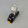
One could go for relay and base arrangement as shown below.

https://www.ebay.com.au/itm/MY2P-HH...7239:m:mJfERCA0RtC7drd-Lgmvx-w&frcectupt=true
 

Attachments

  • Relay&Base.jpg
    Relay&Base.jpg
    41 KB · Views: 3
Thank you very much for your help. So, its power in to the relay from motion sensor, and out to the light. Sensor sends juice to relay, relay closes and lights go on. Sensor off, relay opens, lights off.
Excuse my extreme ignorance, but with the relay in the pic you sent, it would be common in to the lower left terminal, out from lower right, power in upper left, out upper right?
Let me try that again...
Thank you very much for your help. So, its power in to the relay from motion sensor, and out to the light. Sensor sends juice to relay, relay closes and lights go on. Sensor off, relay opens, lights off.
 
Sorry. Ignore my previous, except for the thank you part. I reread your post and it became clear. Thanks again.
 
Top