Maker Pro
Maker Pro

Two stage class A amplifier

Hello.
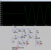
I simulated a two stage amplifier and I have a question regarding it. In simulation when the signal is applied the output of q2 shoots out to Vcc 12V then it stabilizes around operating point, why does it happen?

Vcc 12 V
Freq 27 kHz
input signal sine wave 50mA peak to peak.

Blue line is Q1 colector output
green is Q2
 

Attachments

  • Sim.jpg
    Sim.jpg
    146.9 KB · Views: 133
Why is the value of C4 500 times the values of C2 and C3?
Why are all the resistor values so low causing their currents and the transistor currents (and heating) to be so high?
 
This is my first amplifier design, I simulated it to try to understand how it works. Random C values are there because i tried to mess with them to check if they are cousing q2 12V jump. Values for resistors are low because i will not build this version of amplifier so energy losses are not my concern at this stage.
 
I tried simulating your circuit and it worked perfectly but I cannot read your "tran" on your post. You have a start delay of 0.1m that I have never used.

The simulation is not real because its capacitors are already charged when the sim begins.
 
Your emitter resistor bypass capacitors C2 and C3 have their value too small so they are attenuating the 27kHz signal but are passing the fast acting higher frequency pop at full amplification.
I increased their value from 0.1uF to 1uF and now the pop has less level than the signal.
Your C3 is my C4:
 

Attachments

  • transistors with turn-on pop.png
    transistors with turn-on pop.png
    27.3 KB · Views: 135
Top