Maker Pro
Maker Pro

Troubleshooting Arduino + Heart Pulse Sensor Circuit

Hello all, since you all were so helpful with figuring out how to wire speakers together, I'm hoping maybe you could also help me with this other project I've been stuck on....

I'm working on a project where an Arduino Uno uses 2 heart pulse sensors to trigger 2 solenoids (Sensor A triggers Solenoid A, Sensor B triggers Solenoid B) and is powered by one external power supply.

This is the pulse sensor I'm using: http://pulsesensor.com/
This is the solenoid: http://www.sciplus.com/p/POWER-DOOR-LOCK_47851
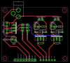
I'm attaching the schematic below and arduino code.

My friend drew up a schematic of what it should look like, but when I wired everything together it didn't work and now both of my pulse sensors don't seem to be working at all.
sad.gif


Link to video of what the circuit/code did do: https://drive.google.com/file/d/0B6GJZjLN3rhwNXVaY2JJUnBXbXM/view?usp=sharing

So I wasn't totally sure if the problem was the code, the schematic, or my own flawed wiring, but I posted on the Arduino forums my problem and this was a response I received:
"Your ground wiring is deeply flawed I'm afraid.

You are passing the 5.2A ground return from the solenoids through thin traces and directly
routing these to the sensor grounds.

1) Ground and power traces need to be wide so they have low inductance, and also need to be
wide for high current as here.

2) Never use the same ground wiring for high current loads as sensors - run these separately
except at one common point, the Arduino ground pins. There should be a thick set of traces from where
the 12V + ground comes in to the solenoid loads. There should be separate traces for 5V and ground
to the sensors, so that transients on the high current wiring doesn't affect the sensor. This is
probably why they are dying.

3) Keep the sources of interference well away from sensitive analog wiring. Using analog pins to drive
out to the MOSFETs isn't a great move, you'll always get some crosstalk from traces that run side-by-side
especially without a ground-plane.

4) Ground planes are very useful, use them whenever possible. You ideally need two ground plane
sections here, one for sensors, one for high current load side of circuit.

5) You don't need 1200V freewheel diodes, 20V is plenty - they do have to take the 2.6A peak
current of the solenoids though."

So seems the problem is the schematic. Now the problem is, I need help understanding this response, or you can add your own input to of course. I am a novice so I can't read schematics very well, but I can understand a parts layout.

Here are my questions in response to this feedback...
1) What are traces? Does it mean I need to be using a thicker gauge wire than standard jumper cables? What gauge do you recommend?

2) So does this mean the grounds from the RFP12N10L's should connect to the arduino ground pin instead of the sensors?

2/3) What should the new parts layout look like with the changes of the ground and power traces?

4) What is a ground plane?


Thank you!

Cadence - parts layout (rev A).png Cadence - schematic (rev A).png
Arduino Uno Code:
Code:
/************************************************************************
  Cadence
  ========

  DESCRIPTION:
    Actuates two solenoids to hit snare drum when heartbeats are found
    by two Pulse Sensors.

  REQUIRES:
    1 x Arduino Uno
    2 x Pulse Sensor Amped - http://pulsesensor.com/
    2 x Solenoid driver circuits with gates attached to pins defined by
        SOLENOID1_PIN and SOLENOID2_PIN below
   
  INSTALLATION + USAGE:
    1) Upload sketch to board 
    2) Build solenoid driver circuits and install on board
    3) Install Pulse Sensors
   
**************************************************************************/

// Pins of all inputs and outputs
#define  PULSE1_PIN  A0
#define  PULSE2_PIN  A1
#define  SOLENOID1_PIN  A2
#define  SOLENOID2_PIN  A3

#define  BUFFER_SIZE  10    // Number of readings to take. More readings = smoother data
#define  HOLD_AMOUNT  100   // Amount in milliseconds to hold solenoids on for

// Variables used by sensor smoothing and beat detection code
int pulseBuffer1[BUFFER_SIZE], pulseBuffer2[BUFFER_SIZE];
int pulseTotal1 = 0, pulseTotal2 = 0;
int pulseAverage1 = 0, pulseAverage2 = 0;
int beatDetected1 = false, beatDetected2 = false;
int lastBeatTime1 = 0, lastBeatTime2 = 0;
int index = 0;

// Peak detection variables
int peakThreshold = 520;  // Minimum value from sensor before beat is detected
int timeThreshold = 200;  // Minimum time between beats. Helps filter out incorrect multiple triggers

void setup() {
  // Get a serial connection going for debugging
  Serial.begin(9600);

  // Set up Pulse Sensor pins
  pinMode(PULSE1_PIN, INPUT);
  pinMode(PULSE2_PIN, INPUT);

  // Set up solenoid driver pins
  pinMode(SOLENOID1_PIN, OUTPUT);
  pinMode(SOLENOID2_PIN, OUTPUT);

  // Set up on-board LED
  pinMode(13, OUTPUT);

  // Initialize buffers to be empty
  for(int i=0; i<BUFFER_SIZE; i++) {
    pulseBuffer1[i] = 0;
    pulseBuffer2[i] = 0;
  } 
}

void loop() {
  // Get most recent sensor data and calculate averages
  readSensors();

  // Detect beats in sensor data
  detectBeats();

Serial.println(pulseAverage1); // troubleshooting

  // Activate solenoid 1 when beat is detected by Pulse Sensor 1
  if(beatDetected1) {
//    Serial.println("Beat detected on Pulse Sensor 2");
   
    digitalWrite(SOLENOID1_PIN, HIGH);  // activate solenoid
    digitalWrite(13, HIGH);             // turn on on-board LED
   
    delay(HOLD_AMOUNT);                 // wait for solenoid to move
   
    digitalWrite(SOLENOID1_PIN, LOW);   // decactivate solenoid
    digitalWrite(13, LOW);              // turn off on-board LED
   
    beatDetected1 = false;              // reset flag
  }

  // Activate solenoid 2 when beat is detected by Pulse Sensor 2
  if(beatDetected2) {
//    Serial.println("Beat detected on Pulse Sensor 2");
   
    digitalWrite(SOLENOID2_PIN, HIGH);  // activate solenoid
    digitalWrite(13, HIGH);             // turn on on-board LED
   
    delay(HOLD_AMOUNT);                 // wait for solenoid to move
   
    digitalWrite(SOLENOID2_PIN, LOW);   // decactivate solenoid
    digitalWrite(13, LOW);              // turn off on-board LED
   
    beatDetected2 = false;              // reset flag
  } 
}

/**************************************************
  Read sensors
  - take new readings and calculate new averages
***************************************************/
void readSensors() {
  // Remove last readings
  pulseTotal1 -= pulseBuffer1[index];
  pulseTotal2 -= pulseBuffer2[index];

  // Obtain new sensor values
  pulseBuffer1[index] = analogRead(PULSE1_PIN);
  pulseBuffer2[index] = analogRead(PULSE2_PIN);

  // Add values to totals
  pulseTotal1 += pulseBuffer1[index];
  pulseTotal2 += pulseBuffer2[index];

  // Advance to next position in array
  index++;

  // Wrap index when it exceeds size of buffer
  if(index >= BUFFER_SIZE)
    index = 0;

  // Calculate averages
  pulseAverage1 = pulseTotal1 / BUFFER_SIZE;
  pulseAverage2 = pulseTotal2 / BUFFER_SIZE;
}

/**************************************************
  Detect beats from Pulse Sensors
  - analyes data from Pulse Sensors and looks for
    peaks of appropriate frequency
***************************************************/
void detectBeats() {
  // Detect beat on Pulse Sensor 1
  // - If sensor values rise above threshold and enough time has passed since last beat was detected
  if(pulseAverage1 > peakThreshold && (millis() > lastBeatTime1 + timeThreshold)) {
    beatDetected1 = true;
    lastBeatTime1 = millis();
  }

  // Detect beat on Pulse Sensor 2
  //- If sensor values rise above threshold and enough time has passed since last beat was detected
  if(pulseAverage2 > peakThreshold && (millis() > lastBeatTime2 + timeThreshold)) {
    beatDetected2 = true;
    lastBeatTime2 = millis();
  } 
}
 
Hi !

Here are a few hints (from an experienced hobbyist point of view) :

1) and 4) The terms "trace" and "plane" refers to PCB (printed circuit board) design. Your diagram seemed to imply that you were designing a PCB so people commented on that assumption.

Traces are the "lines" of copper linking components together and carrying mostly signals.

Planes are usually inner layers of copper inside the PCB. They occupy the whole surface of the PCB and are often used to carry power and ground. For example, on a 4 layer PCB, top and bottom layers would carry signal traces while one inner layer would be the ground and the other inner layer would carry the power. For instance, in your design, the inner power plane could be divided in two sections, one for 5V and the other for 12V. One could go even further and separate the 5V power for the digital components from power for the analog ones. The ground plane could also be splitted in sections (which I won't discuss here as it is a whole science in itself and generates a lot of debates !! Let's just say that from experience, a single ground plane with careful component placement will often do the job).

On two layers PCB, planes can be achieved by "filling the gap" between component pads and traces with copper. One side could serve as power plane and the other side as ground.

2) To accomodate large currents such as 2-3Amps, traces indeed need to be wide (in this case, I would probably use a 100mil wide trace). If you will be using wires, yes, it means that the gauge should be chosen carefully. I think in your case, something around 20-22 should do.

3) If you are not using power and ground planes, keep in mind that you should not be running power and ground wires from component to component. Instead, you should always start from the power source to the devices. It should look like a "spider".

So in your design, all devices needing 5V should have their own wire from the 5V sournce to their power pin. Same for ground. Then all devices needing 12V should have again their own wire from 12V to their power pin. And again, the ground should have their own wire from the 12V source ground to their ground pin. Finally, there should be one wire (as short as possible) linking the grounds of the 5V source to the ground of the 12V source. Components like capacitors, LEDs, resistor, can be wired directly close to their corresponding devices.

Hope this helps !
TechnoGilles

P.S. Note that the circuit schematic looks good. My only comment would be to add decoupling capacitors (esp. 0.1uF) at the sensors (between their power and ground).

The people's comments are more about the PCB/wiring schematic.
 
Last edited:
Hi !

Here are a few hints (from an experienced hobbyist point of view) :

1) and 4) The terms "trace" and "plane" refers to PCB (printed circuit board) design. Your diagram seemed to imply that you were designing a PCB so people commented on that assumption.

Traces are the "lines" of copper linking components together and carrying mostly signals.

Planes are usually inner layers of copper inside the PCB. They occupy the whole surface of the PCB and are often used to carry power and ground. For example, on a 4 layer PCB, top and bottom layers would carry signal traces while one inner layer would be the ground and the other inner layer would carry the power. For instance, in your design, the inner power plane could be divided in two sections, one for 5V and the other for 12V. One could go even further and separate the 5V power for the digital components from power for the analog ones. The ground plane could also be splitted in sections (which I won't discuss here as it is a whole science in itself and generates a lot of debates !! Let's just say that from experience, a single ground plane with careful component placement will often do the job).

On two layers PCB, planes can be achieved by "filling the gap" between component pads and traces with copper. One side could serve as power plane and the other side as ground.

2) To accomodate large currents such as 2-3Amps, traces indeed need to be wide (in this case, I would probably use a 100mil wide trace). If you will be using wires, yes, it means that the gauge should be chosen carefully. I think in your case, something around 20-22 should do.

3) If you are not using power and ground planes, keep in mind that you should not be running power and ground wires from component to component. Instead, you should always start from the power source to the devices. It should look like a "spider".

So in your design, all devices needing 5V should have their own wire from the 5V sournce to their power pin. Same for ground. Then all devices needing 12V should have again their own wire from 12V to their power pin. And again, the ground should have their own wire from the 12V source ground to their ground pin. Finally, there should be one wire (as short as possible) linking the grounds of the 5V source to the ground of the 12V source. Components like capacitors, LEDs, resistor, can be wired directly close to their corresponding devices.

Hope this helps !
TechnoGilles

P.S. Note that the circuit schematic looks good. My only comment would be to add decoupling capacitors (esp. 0.1uF) at the sensors (between their power and ground).

The people's comments are more about the PCB/wiring schematic.

Ok thank you for the detailed explanation! I am not designing my own PCB, I was just going to breadboard it and then solder it to a blank PCB. What are "decoupling capacitors" and how would I add those in? I think I will try rewiring it and post a picture here to see if it's correct....
 
Ok so I wired up the circuit without the solenoids, and the 7805TV got VERY hot very fast. :/ I check the input was 12v, and it was outputting 5v. What could be wrong? Also for the 7805TV, does it matter which side the components are on (like the front or back) (I'm using a breadboard)? Could the capacitors be on the silver side rather than the black side? (I don't fully understand how the electricity moves through a circuit, don't fully understand schematics).
 
I am not sure what you mean by "which side the components are on (like the front or back)"... But it is vital to respect the pinout of each device. Each pin has a unique function and when schematics are made, those pin functions determine how to interconnect components together. So when you physically link the pins together, you have to respect this pinout.

Each pin on each device are numbered from 1 to x (or are sometimes given letters like D G S for MOSFET). Each device will usually have a mark (like a dot or an arrow or a dent) that identifies pin 1. For some other devices, its shape along with the datasheet will help you figure out the pinout. Other devices like electrolytic and tantalum capacitors or LEDs will have a longer lead on the positive side. Reversing the polarity of electrolytic or tantalum capacitors may/will destroy them. Reversing the polarity of a LED will not destroy it but il will not work. Resistors may be plugged in any direction.

Usually, pins on electronic devices can be divided in two categories, and two subcategories for each :

Analog pins : some more positive, some more negative
Digital pins : outputs and inputs.

Electricity flows from more positive pins to more negative pins, as well as from outputs to inputs*. So the connections have a direction.

The regulator being so hot is not a good sign. It means too much current is asked from it. This can be the result of bad wiring or the result of a blown component (whether it is the regulator itself or another component driven by it). Remember that is this case, the reliability of the components may be compromised.

Before going any further, can you submit us your wiring diagram ? Of perhaps draw a plan on how you plan to wire the components on the breadboard and send it to us. Or maybe a picture of the circuit on the breadboard (before applying power !) ? Once we validate the circuit, you can start from scratch with brand new components and you should be in business !

Regards,
TechnoGilles

* strictly speaking this is not entirely true (it depends on the logic level of the signal, whether "0" or "1"). Still, the output is the one "driving" the signal and the input is passive. So one can see it as the signal going from output to input.
 
Thank you, I do understand the importance of the pins. I was trying to describe if multiple points are connected on the same row on a breadboard, if the order in which they are placed in that row matter... sorry hard for me to describe. But here is my wiring diagram....

And link to the actual Fritzing file: https://dl.dropboxusercontent.com/u/53721456/Cadence.fzz
 

Attachments

  • Cadence_bb.jpg
    Cadence_bb.jpg
    205.7 KB · Views: 246
I am not sure what you mean by "which side the components are on (like the front or back)"... But it is vital to respect the pinout of each device. Each pin has a unique function and when schematics are made, those pin functions determine how to interconnect components together. So when you physically link the pins together, you have to respect this pinout.

Each pin on each device are numbered from 1 to x (or are sometimes given letters like D G S for MOSFET). Each device will usually have a mark (like a dot or an arrow or a dent) that identifies pin 1. For some other devices, its shape along with the datasheet will help you figure out the pinout. Other devices like electrolytic and tantalum capacitors or LEDs will have a longer lead on the positive side. Reversing the polarity of electrolytic or tantalum capacitors may/will destroy them. Reversing the polarity of a LED will not destroy it but il will not work. Resistors may be plugged in any direction.

Usually, pins on electronic devices can be divided in two categories, and two subcategories for each :

Analog pins : some more positive, some more negative
Digital pins : outputs and inputs.

Electricity flows from more positive pins to more negative pins, as well as from outputs to inputs*. So the connections have a direction.

The regulator being so hot is not a good sign. It means too much current is asked from it. This can be the result of bad wiring or the result of a blown component (whether it is the regulator itself or another component driven by it). Remember that is this case, the reliability of the components may be compromised.

Before going any further, can you submit us your wiring diagram ? Of perhaps draw a plan on how you plan to wire the components on the breadboard and send it to us. Or maybe a picture of the circuit on the breadboard (before applying power !) ? Once we validate the circuit, you can start from scratch with brand new components and you should be in business !

Regards,
TechnoGilles

* strictly speaking this is not entirely true (it depends on the logic level of the signal, whether "0" or "1"). Still, the output is the one "driving" the signal and the input is passive. So one can see it as the signal going from output to input.
Here is the data sheet for the Mosfets I'm using: http://shpat.com/docs/elfa/07108079.pdf . Upon looking closer... in the parts diagram I have, it looks like both the drain and source pins are connected to ground. Is this correct? Should one be connected to power??
 
I am not sure what you mean by "which side the components are on (like the front or back)"... But it is vital to respect the pinout of each device. Each pin has a unique function and when schematics are made, those pin functions determine how to interconnect components together. So when you physically link the pins together, you have to respect this pinout.

Each pin on each device are numbered from 1 to x (or are sometimes given letters like D G S for MOSFET). Each device will usually have a mark (like a dot or an arrow or a dent) that identifies pin 1. For some other devices, its shape along with the datasheet will help you figure out the pinout. Other devices like electrolytic and tantalum capacitors or LEDs will have a longer lead on the positive side. Reversing the polarity of electrolytic or tantalum capacitors may/will destroy them. Reversing the polarity of a LED will not destroy it but il will not work. Resistors may be plugged in any direction.

Usually, pins on electronic devices can be divided in two categories, and two subcategories for each :

Analog pins : some more positive, some more negative
Digital pins : outputs and inputs.

Electricity flows from more positive pins to more negative pins, as well as from outputs to inputs*. So the connections have a direction.

The regulator being so hot is not a good sign. It means too much current is asked from it. This can be the result of bad wiring or the result of a blown component (whether it is the regulator itself or another component driven by it). Remember that is this case, the reliability of the components may be compromised.

Before going any further, can you submit us your wiring diagram ? Of perhaps draw a plan on how you plan to wire the components on the breadboard and send it to us. Or maybe a picture of the circuit on the breadboard (before applying power !) ? Once we validate the circuit, you can start from scratch with brand new components and you should be in business !

Ok I wired up the whole circuit on perf board and used thicker wire in the 12v areas, nothing seems to be overheating anymore when I plug in the 12v. I also tried to separate the grounds/power lines a bit more from the sensors and solenoids by using your "spider fashion". There still seems to be something not quite right.... I tested with my volt meter, and the 5v and 12v seem to be correct and only go where they're supposed to. I'm really worried about frying my sensors again, so is there a way I can test the mosfets, without plugging in my sensor? I've been not plugging in the 12v source, and just plugging in the arduino using 9v battery pack and then test it with my sensor, and then watch for the arduino LED to light up, like it should when the sensor is triggered. I noticed the LED connected with the solenoid lights up, when a pulse is taken, should this LED be lighting up without the 12v plugged in? Or does that mean something is connected that shouldn't be? Also, I think the code isn't that great, and am going to try using a different code that uses pin 11 and pin 5, instead of the A2 and A3 pins for the solenoids. Is this okay to substitute?
 
Can you amend the code so you fake a sensor input? This will allow you to test the MOSFETS. You shouldn't fry your sensors if you have the correct voltage an polarity connected to them.
Adam
 
Ok I wired up the whole circuit on perf board and used thicker wire in the 12v areas, nothing seems to be overheating anymore when I plug in the 12v. I also tried to separate the grounds/power lines a bit more from the sensors and solenoids by using your "spider fashion". There still seems to be something not quite right.... I tested with my volt meter, and the 5v and 12v seem to be correct and only go where they're supposed to. I'm really worried about frying my sensors again, so is there a way I can test the mosfets, without plugging in my sensor? I've been not plugging in the 12v source, and just plugging in the arduino using 9v battery pack and then test it with my sensor, and then watch for the arduino LED to light up, like it should when the sensor is triggered. I noticed the LED connected with the solenoid lights up, when a pulse is taken, should this LED be lighting up without the 12v plugged in? Or does that mean something is connected that shouldn't be? Also, I think the code isn't that great, and am going to try using a different code that uses pin 11 and pin 5, instead of the A2 and A3 pins for the solenoids. Is this okay to substitute?

If you have 5 Volts going to the output of the regulator from the control board and you don't have 12 volts connected to the input of the regulator then you could get voltage feedback onto the 12 Volt line.
Adam
 
Can you amend the code so you fake a sensor input? This will allow you to test the MOSFETS. You shouldn't fry your sensors if you have the correct voltage an polarity connected to them.
Adam
Hm, I'm not an experienced coder, so I am not sure how to do this... could I just use the Arduino "Blink" sketch and substitute pin 13 for A2?
 
Hm, I'm not an experienced coder, so I am not sure how to do this... could I just use the Arduino "Blink" sketch and substitute pin 13 for A2?
Well this worked! But it totally bypasses the sensor input... but I guess it should be okay then? Do you think I can substitute the analog pins A2 and A3 for Digital pins 11 and 5?
 
Hm, I'm not an experienced coder, so I am not sure how to do this... could I just use the Arduino "Blink" sketch and substitute pin 13 for A2?

No, servos need PWM to work. You will need someone to help you with the code. I am not a software engineer and can only help you with the electronics and any EMC issues you may have.
Adam
 
Top