Maker Pro
Maker Pro

Delco Radio CDM Troubleshooting and Component Identification

Hi all. I have an original equipment Delco AM/FM Stereo Radio from a 1994 Chevrolet Full Size Blazer (I bought it new) that has recently started to give me intermittent problems. About a month ago, the issues were sporadic and tolerable and would solve themselves with a power off and back on of the radio power button. That isn't working anymore like it used to.

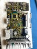
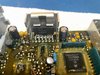
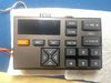
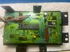
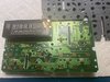
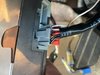
The radio system has two main parts. The control head, with the display and control buttons, which is mounted in the dash, and the CDM (the brain of the system, model number 16169561) mounted under the dash and hidden from view. The CDM has plug-in connections for the upper control unit, an equalizer, a cassette deck, and the four speaker outputs.

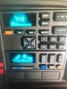
The initial problems started out with the display not changing with the input buttons. The volume level indicator (small downward pointing triangles in a row-see pic) used to raise up and down (move left or right on the display) with the push button volume control; the clock used to work but now it stays at 1:00; the radio station frequencies used to show up on the display when the stations were changed but now it stays on 98.1; the clock used to be able to be set, etc. Additionally, the power button used to turn the radio on and off and it is getting increasingly difficult for that to work now as well.

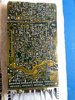
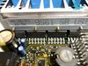
Here is what I have done so far: I have read that the issue is with the Radio CDM that is under the dash. I have seen where repair facilities identify this as the problem component in the system with the issues I am having and it does not look like it is a rare problem. Many others have had the same issues as I am having. I have removed and inspected the CDM for bad solder connections. I have re-flowed most of the solder connections that would typically cause solder joint issues. I have removed and replaced the nine Electrolytic Capacitors with new. I have looked at all of the other components on the PCB and have not found anything that would visually indicate a problem component...no burns, leakage, or other visible damage to anything on either side of the board. The plug-in connections are not corroded or rusted and look to be in good condition. I have tested each pin connection and followed it to the first component location the pin would contact and I have continuity from each pin. I do not have a schematic of the board and do not know if one is available. I have looked for one.

I do not have sophisticated testing equipment and am simply a novice when it comes to these things, but I have gotten lucky several times before and that is why I am here now and that is to seek your advice as to what to test or look for next. I would rather keep the system original, although I do know there are used replacement CDM's available, and I can send this one in for repair, if I can't figure this out with your help.

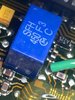
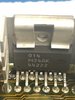
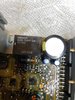
Additionally, there is a small blue box component I am not able to identify. The markings show "SFH 450 F3 Cm C." A pic is attached. Is that possibly a relay of some sort? The other larger black box is a relay and I have removed and tested it for proper operation. It works as it should. I have not removed the blue one. The reason I am curious about the blue one is in the case of a failing/failed relay, it may not be allowing the proper signals to get to the control head to utilize the power and control buttons??? Just guessing here.

Sorry this is so long, but I figured I would give you as much info as I had from the beginning. There are pics attached too. I can take better ones, or more specific ones of the board, if needed. Thanks, in advance for any helpful replies. I am hoping someone out there has experience with this particular unit and can point me in the right direction for component replacement.
 

Attachments

  • IMG_9208.jpg
    IMG_9208.jpg
    47.7 KB · Views: 11
  • IMG_9207.jpg
    IMG_9207.jpg
    277.7 KB · Views: 12
  • PCB Top.jpg
    PCB Top.jpg
    89.4 KB · Views: 15
  • PCB Bottom.jpg
    PCB Bottom.jpg
    98 KB · Views: 13
The 'SFH' thing is a filter for the radio signal path and won't be faulty - leave it well alone!

Given the fault symptoms I'd be looking at the control head rather than the main unit. Dodgy keypad contacts (common) and potential issues with a data signal between the main unit and the head (less likely).

Anywhere there is physical movement, pressure, potential for water ingress etc - it all points to the control head (dash controls). If you can fit a replacement dash control panel then that's the obvious way to go but post pics of those controls (front and back) and some internal shots if you can.
 
I second the keypad contacts as a prime suspect and would have been my first thing to check and clean.
The graphite on the bottom of each silicone button might have worn away or the actual traces on the board itself.
I doubt this unit has tactile switches but it’s not impossible.

Martin
 
kelly_eye and Martaine2005, thank you for the replies. I did initially suspect the control head contacts as well, however, when I was first checking into repair possibilities, I was advised by the repair facility that the CDM was the problem component. That was the component they wanted to have me send to them after I provided the malfunction information, and from what I have read, that is the component others with the same problems have sent in for repair. Additionally, others have had the same frozen clock and frequency issue and have solved it by replacing the CDM from a junkyard vehicle. I would rather try and fix mine before resorting to having it repaired by someone else, or getting a replacement CDM.

Most of the control buttons (power, volume up and down, seek, scan, tune +-, and recall) have stopped having any effect on controlling the display. The display will show "scan" when the scan button is pushed and the set button shows "set" on the display. Most of the buttons will still operate their respective radio functions. The volume does increase or decrease when the volume + or - is pushed, etc. That wouldn't seem to me to be a corrosion or deterioration issue. There have not been any liquids near that component and I live in a desert climate. I will take the control head out and take a look though, if for nothing else, so I can continue the troubleshooting on the bench instead of going back and forth to the truck every time I want to check my work.

Another thing I noticed today. When the truck is not running, the control head buttons don't seem to have the same effect on the stereo volume, scan, tune, power, etc. buttons as when the truck is running. When the truck is running, the buttons adjust the associated functions of the stereo system fairly well, but the display still does not respond to the inputs. When the truck is not running, the buttons are intermittently adjusting what they are supposed to. But the radio frequency and the clock are still not adjusting or working correctly at all. They stay at 1:00 and 98.1. I tested the voltage at the CDM when the truck was not running and am getting about 11.9vdc. With the truck running I am getting 13.5+. Now I am wondering if I have a failing voltage regulator that is possibly not supplying the correct output voltage to the display portion of the CDM.

Whatever it is, the "adjust the display signal" is not making it to the control head unit from the CDM.

I think I have found the voltage regulating component, but I still have to make sure it is before I start trying to test it. Not quite sure, but it looks like it could be and the first pin on the left is connected to a +12v constant power from the battery. I have attached a photo of the possible component. I haven't been able to locate the data sheet for it or it at all, yet.

Thoughts?
 

Attachments

  • IMG_9229.jpg
    IMG_9229.jpg
    143.2 KB · Views: 14
  • IMG_9204 (1).jpg
    IMG_9204 (1).jpg
    53 KB · Views: 16

Harald Kapp

Moderator
Moderator
This component (M34AK) doesn't look like a typical voltage regulator. It is more likely the power amplifier.
 
I HEAVILY THIRD the keypad contacts . . . . .from your explanations . . . . each discrepancy is related to having previously made a keyboard contact . . .which apparently, did not electrically connect.

Secondly
. . . . that POWER AUDIO IC shown is an
LM3886TF
and not being related to your problems, as was also the blue cased 450khz ceramic filter, it relates to your AM radio receiver portion.


Send pics, of its interconnecting wiring / connectors and the actual keyboard propers board.
Expect each related pushbutton key to be constructed in this order, or they may be combined as one big mat..
upload_2022-3-15_4-43-14.png

Final thought . . . . . that display resembles a VFD type , with a turquoise color of display digits.

" One a 'dem . . . .its a look a like a dis "

upload_2022-3-15_6-31-45.png

Take note of my RED arrows that align with some fine grid wires ( really filaments) that run across the front inside of the display.
May take a BRITE flashlight to be able to see them.
If that technology is being used for the clock and receive frequency display . . . . it requires a DC-DC converter power supply to feed it with two voltages. One is being for that displays negative forty'ish voltage and the other is being the 5'ish logic voltage for its electronics .
Possibly some electrolytic filter capacitors used in its associated power supply have finally / probably ESR'd out

73's de Edd . . . . .

upload_2022-3-15_4-45-38.png

.


Last edited:
As mentioned and re-iterated by others, the SYMPTOMS point to the keypad and/or the communications link between the keys and the main unit. The keypad will be scanned electronically and converted to a serial data stream - same as the information coming back from the control unit to the display - so the common issue is the data. It's either corrupt or missing but since SOME buttons work we can only assume the data path is working else nothing would.

This only leaves the individual buttons as a potential point of concern. It's relatively simple to test/check with the board out of circuit. The only possible way it can be something un-related to the buttons is if the keypad and display are controlled 'directly' from the main unit - this would involve having a multi-way ribbon cable between the two units and this isn't common practise, especially in a motoring situation where environmental and vibration is a big issue.

Lastly, the old 'capacitor plague' could be the cause. Capacitors are well known for 'drying out' and causing issues - both random and permanent - and the cure is simple (he said.....) by replacement.
 
Thanks again guys. As stated earlier, ALL of the electrolytic capacitors on the CDM Board and the Control Head Unit (CHU) have been replaced with quality replacement caps that were tested before installation. I'm fairly confident the Caps can be ruled out.

Today, I removed the CHU and inspected the contacts. The CHU is in very good condition and showed no signs of carbon contact wear on the rubber pads, no deterioration of the contacts on the circuit board, or any indication of liquid penetration. See the pics. In any case, I swabbed the PCB contacts and the carbon contacts to ensure they were clean. The pics were taken prior to cleaning anything. After re-installation, the same problems noted above were still there. I'm fairly confident I can rule out dirty or deteriorated push button contacts.

Just so I am making myself clear here, the buttons DO control the radio functions. The volume goes up and down when I push Volume +-, and the frequency does change when I hit Tune +-, etc., it is just the signal that should change the display is, for some reason, not getting sent to the display from the CDM, which is what I have been told is the problem component. That tells me the push button mechanical contacts shouldn't be the problem. So I suppose I have to look for the circuit on the CDM PCB that would receive the input from the CHU and then send the signal back to the display, right?

And I see where Mr Kapp mentioned the component I sent a picture of what I thought was some kind of voltage regulator is not one, but is a "power amplifier." I am assuming he meant for the speaker outputs, but there are four other components attached to the large heat sink that I would have thought would have been the "power amplifiers" for the four speaker outputs. See the pic. Because this CDM supplies the voltages for the cassette player, and equalizer, and the CHU, I thought maybe that was what the M34AK may have been for, because each one of those components only plug into the CDM and maybe this component (M34AK) was simply similar to a "bus bar" for the other components' power supply. I think this because there are no other power supply wires to any of the other components. Mr Kapp, do you still think that component (M34AK) is a "power amplifier?" Or am I misunderstanding just exactly what a power amplifier does?

Here is another question. When relays (the Omron G8S-114P-SB on this board) start going bad, do they start to lose the efficiency of current/voltage transfer they had when new? The reason I ask is because when the truck is running, the power switch seems to work fairly well, but when the truck is not running, the power switch often will not power up or off the radio. I don't know if this relay is activated by the power button or not, but it would make sense to me that it would. Am I wrong here?

Again, thanks for your help so far.
 

Attachments

  • IMG_9236.jpg
    IMG_9236.jpg
    106.9 KB · Views: 12
  • IMG_9235.jpg
    IMG_9235.jpg
    117.2 KB · Views: 13
  • IMG_9239.jpg
    IMG_9239.jpg
    105.8 KB · Views: 12
  • IMG_9243.jpg
    IMG_9243.jpg
    155.8 KB · Views: 13
  • IMG_9244.jpg
    IMG_9244.jpg
    77.7 KB · Views: 14
  • CHU To CDM.jpg
    CHU To CDM.jpg
    47.9 KB · Views: 13
So I suppose I have to look for the circuit on the CDM PCB that would receive the input from the CHU and then send the signal back to the display, right?
Correct.

You can easily Google part numbers to ascertain a devices function. We do!

I tested the voltage at the CDM when the truck was not running and am getting about 11.9vdc. With the truck running I am getting 13.5+.

This isn't exactly perfect - I'd expect a 'good' battery to deliver 12.6V with the vehicle at rest and rise to 14V when charging (engine running). If you can run the unit on the workbench you could simulate a good versus bad supply voltage situation to prove this as a potential problem-maker.

The unit should be a lot more tolerant of supply voltage changes though - I'd expect a unit to operate perfectly down to 10.8V before showing issues so maybe a supply line is the problem?

Either way you need to test under varying supply voltage conditions and check internal regulator output voltages to see if there is any 'drop-out'. I suspect this isn't the real issue though.

Both the control head and main unit talk via a serial data path but getting a partly corrupted data stream (only some signal conditions like volume up/down but not display data information) is unusual and would point to a CPU/software issue with the main controlling CPU swap-out being the potential repair route.

Do you have any technical information on the unit (schematic etc)? This would make things a lot easier else you're going to be looking at serial data streams to check for data loss and/or signal integrity (i.e. correct logic levels and, potentially, synchronising signals).
 
Thanks again for the reply. The voltage issue on the truck is simply because it isn't driven regularly and the alarm system tends to draw the battery voltage down. It charges fine and holds the charge after being driven.

I have searched for a schematic or a service manual for the Delco CDM Model Number 16169561, but am not having any luck in finding one. Sometimes I get lucky with an FCC Search on an electronic component, but not this time.

In the past, the CHU power on and off button worked fine, even without the vehicle running. I can hear the relay activate sometimes when I power on and off and I would think it would be consistent at the lower voltage. When it does "click" on, the radio comes on and the CHU comes alive, but still with the same issues described above.

I'm sure the repair facilities know just exactly where the problem lies, since they have quickly quoted a flat rate repair fee. It will be worth it, if I can't figure this out on my own, but I'm in no hurry, and this is more of a challenge to me than anything else. I just have to hope I don't cause more damage while messing around with it.

As far as your last paragraph, that's just way above my skill and test equipment levels here. :) I am a "find the bad component and replace it" type of electronics repair guy. Sometimes I get lucky, and sometimes I don't. I am ahead in that regard though, probably because I leave it alone and think it through, and come up with other possibilities in the mean time. I'm not done with this one. But I am still curious about that M34AK Component and just exactly what it is.
 
The power switch itself won't operate the relay directly. Quite often this activates a 'wake up' signal to the CPU that itself activates the relay but you could at least measure the voltages on the relay contacts as you activate it and look for a volt-drop - which would prove the relay contacts as being defective.

The relay is a common design item too and you could worse than simply replace it to alleviate the necessity of test/trace.
 
Top