Maker Pro
Maker Pro

Treadmill belt won't spin.

Hey All,

I am really struggling here and I need some direction please. I had a treadmill that was working perfectly fine. I moved it to the basement and now the belt won't spin (tilt and everything else works perfectly).

* The motor and belt DO turn when I connect a 20v drill battery to the terminals.
* If I spin the motor while running a program, I do not get an E1 error which lets me know the magnetic sensor is still working.
* All the LEDs light on the board, a red light turns on when a workout program is started, it switches off when I get the E1 error (no motor sensor).

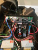
When I start the basic program which is half a MPH walk, I put a multimeter on the motor terminals and I get a voltage reading around 1.98 volts. Is this enough power to turn the motor? Maybe I am missing something entirely but it just seems so odd that simply moving the unit caused this. Any advice is much appreciated!!!!

I have attached a picture of the board and circled where I took the voltage reading.
 

Attachments

  • 20201225_132016 (1).jpg
    20201225_132016 (1).jpg
    375.3 KB · Views: 12

Harald Kapp

Moderator
Moderator
1.98 V is definitely not enough to power the motor of a treadmill.
Maybe just some lose connections due to the movement of the unit? Check all connections, the ones to the controller on the handlebars, too.
Lose connections seem to be a common problem judging by the many threads on this topic.
 
I have checked all the connections, I dont see anything wrong. They are all plugged in, healthy pins, nothing bent. I am at a loss on what to check next. Bad transformer? The one one the right with 5 wires? Any suggestions on anything I can do to get me closer to the issue would be appreciated!
 
I dont see anything wrong.
As suggested, a loose connection.
Have you disconnected and reconnected all terminals and connectors?. Including handlebar display?.
Was the treadmill lifted downstairs or bumped downstairs?.
Check solder side of PCB while wiggling the larger components on the board. Vibration or heavy knocks may have broken a solder joint.
Moving an item shouldn’t cause it to stop working. But if lifted by wires can cause issues. Check all external wires too.

Martin
 
I have disconnected and reconnected all terminals already (including upper and lower handlebar connections).

The treadmill was lifted down the stairs, no bangs or drops during the move.

I have removed the PCB and attached pictures. I don't see anything that jumps out as bad but another scan would be greatly appreciated in case I am missing something to a trained eye!


20210107_084608.jpg 20210107_084513.jpg 20210107_084523.jpg 20210107_084533.jpg
 
Do you have a multimeter?

If so check the resistance of the large white ceramic resistors on the bottom side.

Check the solder joints on the diode (with the strange potting and shrink tubing on the heatsink) above those resistors, and check the diode voltage drop to make sure the diode is good. One of the joints looks strange in the photo.

Don't know what sort of transistor or FET is used for the driver, also mounted to the heatsink. There are ways to check depending upon what it is

P.S. Please don't start multiple threads on the same problem.
 
I'd check your relays too. Sometimes they can be damaged from bumping around or maybe the arm had was already weakened from use and then moving it around even a little was enough to finish it off. Never worked on a treadmill but I see it a lot in automotive boxes.
 
Sir atcsharp . . . . .

On your very 1st photo , I saw the 2 corner screws missing . . . . . . .and visualized your dismay in then seeing that the board would then not budge.
NOT TO BE.
After some further exploration you then discovered the need of mechanically decoupling from the heat sink and your ensuing encounter with some messssy white " pookie ".
Now you have the board free and are being seriously ready to save yourself some $200 +.
Now my first question is if the unit would adjust the ramp elevation,as that is done by its motor and the two BLACK ice cube relays at the pics front foreground of the next to last pic. That probably was true, since your unit is an older model that uses the two shown power transformers for making up linear power supplies.
Also, your having display activity / capability is also indicative of their functionality.
Your BIG treadmill motor is being powered by 120VAC coming in, being fused, and then passing thru the contacts of a power relay and then going into the large, BLACK, side ways mounted, square cased, Full Wave Bridge rectifier.
The then produced DC voltage from it is then routed to the GIANT, center chassis BLACK E-capacitor which stores the 160-170 ish volts DC supply which will pull way down to a reduced lower level by the progressive loading effect of it when running the main DC tread motor.
That voltage is applied thru a power IGBJT transistor which is physically located in a direct line behind that E-cap. Also, to its side is a power damping diode which is responsible for limiting / clamping down the constant stream of high voltage, inductive derived spikes which occur both from motor commutator actions and from a vari-pulse width train that is driving that power IGBJT.
Now for documentation, get the part numbers of the power IGBJT and its similarly cased damper diode, being just beside it, then I can Edd-u-cate you on further testing of the whole unit

Thaaaaaaassit . . . . jes' fer now.


73's de Edd . . . . .


My wife just made me join a bridge club . . . . . . I jump off next Tuesday.


.
 
Top