Maker Pro
Maker Pro

Thrustmaster T300 PCB component ID help

Good Day,

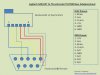
I have a Thrustmaster T300 racing wheel. It won't detect the pedals. Looking further, it appears there is no 5V to the pedals from the pcb. Attached is a pic of the suspect area (I found the pic on this forum. It is a clearer pic than I can take.) I think they are diodes. Marked on the board as esd1(?) the rest of it is covered by the sticker. All marked with an ESD are the same. I have one that is open in both directions the others are open one way, continuity the other way. It is the one directly above the red wire which is 5vdc to the pedal and appears to be the only connection to the pin.. The part is marked with an AB. Any ideas what I can use to replace it to test?

Thanks in advance.
 

Attachments

  • t300 pcb.jpg
    t300 pcb.jpg
    368.5 KB · Views: 323
Yes! Thank you. Its marked AB so it looks like its this one: PESD3V3L1BA. Doesn't seem to be in stock anywhere. Is there anything I could use as a temporary replacement just to test if there are any other problems? I got this wheel at an auction for a steal. I would love to get it working again.
 
Sir apptech . . . . .


It's just being a transient absorber / protector, which I don't expect to be "loading down" and pulling your 5VDC down to nuttin'.
The most revealing test would be to just lift it out of circuit and then test for your 5V. . . .which I still certainly feel . . . . . . that it will not then magically appear.

Instead, I would suspicion the non presence of the +5 to be related to the circuitry in the right bottom corner of the boards components.

Power up and DC voltage probe all of the solder connections in that cluster to see if +5 is found on any of those solder connections.

Just for notification, in the top right corner there is a square pad in the mix of six, that has a solder splash upon it, however I feel that it has not penetrated the hard green resist around it to make a secondary connection.

I just done a re read of all . . . . . I found the pic on this forum . . . . . so actually, it's being THEIR problem, not YOUR boards problem..

73's de Edd
.....
 
Thanks again. You know your stuff. I'm getting in over my head here. The diode in question is the only thing that connects the pin from the red wire to the board. The diode is open in both directions so removing it would be no difference right? The limited info I can find for this board(attached) shows that the red wire should be +5v. The pedals are powered from this board only. Can I jumper the diode? I assume I can't . I'll probe around in the corner you mentioned for now.
Thanks for humoring me with this.
Update: I found 5vdc from the left pin on c90 to the red wire to the pedals with the pedals connected and 1.6vdc with the pedals disconnected. The pedals are confirmed working with another wheel and I tried new pedals with this wheel and they are not recognized either.So it seems like it may be not a connection issue. Also the light goes from red to green when I plug the pedals in so I guess it is powering them and recognizing them . D'oh. I was so hoping it was that diode.
 

Attachments

  • rj12pinout.jpg
    rj12pinout.jpg
    51.7 KB · Views: 154
Last edited:
Top