Maker Pro
Maker Pro

The Theremin Stretch

I decided to try to build this and have it all breadboarded up.

https://www.youtube.com/watch?time_continue=819&v=oRhO0MJIl58&feature=emb_logo
.
The schematic for it is at 6:50 of the video.

It is a Theramin- which is a musical gadget of sorts. It makes zany noises when your hand moves toward it.

To see Lez Zeppelin use, one, see 6:15 of this videohttps://www.youtube.com/watch?v=JoTyCwRkm3I

In any event, in the video, the builder of the circuit uses a TIS58 JFET transistor (which has long been discontinued).

I am using a MPF102 JFet instead. As the maping between what he used, and mine is slightly different, I adjusted my wiring accordingly. More specifically, in his JFET, the ordering is Drain, Source. Gate. In mine, it is Drain , Gate, Source.

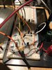
So I very carefully put all this together, and used flar coinnecting wires when I could, so as to keep the breadboard tame.

But, surprise, it's not working.

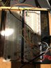
Any ideas on what to check? I have include pics of my breadboard but I realize it is not easy to look at pics.

Some of the things I am wondering about. I pulled a telescopic antenna from an old mid sized transistor radio i had. The antenna seems to only have one lead coming out of it. Could the antenna be the issue?

In order to keep things withing reasonable cosyts, i ended up buying these variable capacitors:
https://www.amazon.ca/gp/product/B07DDHV5V6/ref=ppx_yo_dt_b_asin_image_o02_s00?ie=UTF8&psc=1

I think they are intended for Audrino, but they should work regardless right? They did not have the exact spec the ciorcuit calls for- it calls for a 4-50pF. The ones I ordered had a 40pF and a 60pf- but not a 50pF. I chose to use the 60pF.

Any thoughts?

Thank-you


.
 

Attachments

  • IMG_4480.jpg
    IMG_4480.jpg
    312.6 KB · Views: 4
  • IMG_4479.jpg
    IMG_4479.jpg
    352.8 KB · Views: 3
Thanks Harald and Bertus. I should have read the webpage that Bertus cited in detail. The designer of this circuit goes to great lengths to answer a slew of questions on those pages. From reading it, it looks like my parts need changing. The JFET i chose, for example has a parameter of 0 to -8, whereby the maker says it should be -3 to 05 or something like that. Likewise, i probably have to put capacitors in series, as suggested, or look for the proper variable capacitor. This may take a while as I have tollok for the right parts and re-read the web pages.
 
Thanks. I think I have concluded that the breadboard is posing a problem in of-itself.

In the original schematic and write up, the design calls for a V31 7BL06 Voltage regulator, but I don't see that being talked about in the video.
 

bertus

Moderator
Hello,

On the video you see that the theremin itself is running on +6 Volts and the LM386 is running at +9 Volts.
There must be a voltage regulator that brings down the voltage from +9 Volts to +6 Volts.
A LM78L06 can do this, but will only work until 8 Volts from the battery.

Bertus
 
Here's where I am at. I read through all the posts on the original web pages and the JFETs I am using are said to be an updated version of one that is listed as working. So, it also holds that thre JFETs I am using will also work.

I turn the circuit on, and plug it into a guitar amplifier, and there is no sound whatsoever. There is no electrical buzz at all, which is good i guess, but there is only silence. Given that the JFET I am using is said to be okay for this circuit, do you think it may be the variable capacitor being of the wrong value?
 

bertus

Moderator
Hello,

When there is no sound at all, I am afraid that the oscillators do not work.
The working is based on the frequency difference of the two oscillators.
As the oscillators should work at about 410 kHz, there is also a chance that they are to far apart in frequency and the circuit is putting out a signal that is beond hearing.

What voltage do you measure across R12 and R42?
I would expect an voltage of about 1.5 Volts.

Bertus
 
Some Jfets draw a high current and other Jfets draw a low current even when they have the same part number. The datasheet shows the range of current. The circuit resistances for the biasing must match the Jfet, or the Jfet actual current must match the biasing resistances. Then the Jfets must match.

Since the two oscillators must match perfectly for the capacitance of your hand to change the frequency of the oscillator with the antenna a very small audio change in frequency then the circuit capacitances must match which is impossible when using a breadboard. But the author claims he did it.
 
Hello,

When there is no sound at all, I am afraid that the oscillators do not work.
The working is based on the frequency difference of the two oscillators.
As the oscillators should work at about 410 kHz, there is also a chance that they are to far apart in frequency and the circuit is putting out a signal that is beond hearing.

What voltage do you measure across R12 and R42?
I would expect an voltage of about 1.5 Volts.

Bertus
Bertus- sorry, I did not see your question about voltages, until now. I will measure and report back.
 
Bertus asked: What voltage do you measure across R12 and R42?
I would expect a voltage of about 1.5 Volts.


I placed my negative and positive multimeter leads, one on each side of each resistor. In both cases, I got 0 volts. My variable power supply was supplying 6 volts to the circuit. So, there is no voltage where the expected 1.5 volts was to be.

Here's where I am at. I read AudioGuru, Bertus and Harald's comments.

The easiest way to eliminate the breadboard issue, is to build this circuit on a PCB. I am prepared to do that, however, I don't want to do that until the circuit is problem solved.

I understand from reading this thread, that the JFETS draw certain current levels. In my case, I am using three identical, new MPF102 N-CH RF SS TO92 s. This is the datasheet I found for them:

https://www.mouser.com/datasheet/2/149/MPF102-889956.pdf

Prior to moving forward, I need to know how to properly configure the components.

Is it the JFETS themselves that are not in keeping with what this circuit needs. if so, what JFETs could I get that will work?

Is it because of the JFETS that I am not getting the expected voltage readings on R12 and R 42, or is that something else?

Any ideas/advice?

Thank-you
 

bertus

Moderator
Hello,

From the pages I gave you:
Every NJFET with a Up between -1.5 and -3V and a Idss between 2 and 6mA should do the job.

Your MPF102 shows -0.5 to - 7.5 Volts and a pich-off voltage of - 8 Volts.
You can have fets in the mentioned range, but also have fets that fall outside the range.
The given 1.5 Volts is at about 3 mA.

The jfet will not bias correctly now.
Here is a page that explains the jfet bias:
https://www.theengineeringknowledge.com/jfet-biasing-method/

The oscillator uses the selfbias with the gate grounded.

As for the jfet, I would try a J113 at mouser.
It is mentioned here , as possible candidate : http://thereminworld.com/forums/T/29231?post=209294#209294

Bertus
 

Attachments

  • jfet-j111-j112-j113a-interfet.r00-1649110.pdf
    295.8 KB · Views: 0
The Jfets you purchased are probably not identical. Some have a 2mA spec and others have a 20mA spec. You need to test them and hope to match them if you bought extra ones.
 
Thanks guys. Bertus- I can buy 20 J113's at Mouser for $8.23. Problem is, there is a $20 delivery charge tacked on.

I need to find a cheaper option. I'll look around. I'll also see if the local electronics shop has them.

In terms of the article, I looked at it, but plan to read it when I have the required time, as I think it's worth reading carefully.
 
Hard to find the J113s locally. I called another store and they said it has been replaced by the NTE469, but they don't have those either. Hmmmm

If I can find something at that link above (Sayle Elecrtronics), that would be my best bet as I can simply go there and buy it
 

bertus

Moderator
Hello,

I see the J110 at the shop.
You could try that one.

Bertus
 

Attachments

  • J110-D.PDF
    52.6 KB · Views: 0
Top