Maker Pro
Maker Pro

That awful "yellow glue" - How to remove it?

I found two archived threads about the notorious yellow glue, often used on power supply boards manufactured in Asia, that eventually turns brown and conductive:

https://www.electronicspoint.com/threads/that-awful-yellow-glue-on-circuit-boards.61364/
https://www.electronicspoint.com/threads/yellow-glue-strikes-again.238455/

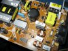
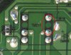
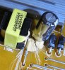
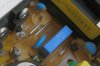
I recently repaired the power supply board of my Samsung 24" LCD monitor (purchased new in 2008) by using an exacto knife to saw some grooves in the glue, which was a light tan color. There'd been an electric arc underneath a small transformer. The glue covered that side of the transformer and some neighboring components, so I sawed some "fire breaks" in the glue so its undesirable conductivity would no longer connect any of those neighboring components to the transformer or each other. That appears to have eliminated the arc and the monitor works again. Unfortunately, there's a lot of glue elsewhere on the board, mostly yellow or light tan, which I assume are ticking time bombs. So I'm wondering how to remove the rest of the glue without laboring for days and with minimal risk of damaging the glued components.

Some threads at Badcaps.net say to soak the glue in isopropyl alcohol, but I don't know if that will work before the glue degrades and turns brown. In the first archived thread linked above, the last message (written by Ray in 2005) contains the following: "You can't get it off until it starts discoloring. I've tried." Unfortunately, Ray didn't say how he'd tried.

I tried applying 91% isopropyl alcohol (recommended at http://www.badcaps.net/forum/showthread.php?t=34692) with a q-tip to another patch of glue for a few minutes but that didn't help me scrape it off with an exacto knife.

How about using a moto-tool with a small filing bit to remove the glue? I'm wondering whether to buy and try the following one at Amazon, which costs about $24:
Dremel 7300-N/8 MiniMite 4.8-Volt Cordless Two-Speed Rotary Tool
https://www.amazon.com/gp/product/B003TU0XFU

Any suggestions? Thanks in advance!
 
You'll probably do more harm than good with a Dremel. That glue is a mastic type adhesive, similar to what's used to adhere vinyl flooring. I haven't tried this yet but something oily like paint thinner, deodorized kerosene or one of those orange oil-based adhesive removers might work.

You'll need to be watchful of damage to plastics, components, silkscreen on the board and everything else. You'll also need to be prepared to remove the residue from these products with isopropanol, reflow any stressed solder joints and fixture the components anew with electronics grade silicone compound.
 
@Sunnysky: Thanks, I'll check for a high voltage differential at that transformer and its neighboring components, and then check the voltages at other glue spots. In addition to high voltage, I assume locations with high heat are also suspect. The glue gobs that have turned the darkest color are presumably highly suspect. Is it correct to assume that the glue breakdown will accelerate after it begins to conduct, due to an increase in the heat there due to the current through the glue?

@KJ6EAD: Thank you too. Regarding the Dremel or other rotary file tool, suppose I use it to remove most of the glue, but allow a thin layer of glue to remain in order to keep the Dremel from touching the board or components? That would presumably significantly reduce the amount of labor needed to remove the remaining glue with a solvent and/or hand tools. Where you wrote about "stressed solder joints" what stresses did you mean? In particular, do you think using the Dremel to remove all except a thin layer would stress solder joints?
 
The risk with the Dremel is slipping and scuffing something. The mechanical stress of pushing and prodding with whatever cleaning tools you use may crack a solder joint or even break a lead.

I like Sunny's idea about leaving the low voltage areas alone.
 
- unavoidable contaminants in dielectric adhesive are known to cause static discharge internally or PD. If excessive, and visible, we call it corona.

Silicone RTV is the best insulation thermally and electrically but not a strong adhesive, more a sealant.

Polyurethane is The best adhesive and there are many grades.

If it does not arc, a better moisture barrier would be RTV after cleaning and drying.

You might be able to make the old glue brittle with "cold-spray" in a can (-40'C) , for easier removal.
 
Last edited:
@Sunnysky: (1) What does the acronym "PD" stand for, where you mention static discharge? (2) Are you recommending polyurethane to replace the old glue? (I'm assuming the purpose of the glue is to prevent components from vibrating.) (3) Where you wrote "if it does not arc," does "it" refer to the power supply board or the RTV? If "it" refers to the board, what is your point? If "it" refers to the RTV, is that another way of saying choose a non-conductive grade of RTV? (4) Are you recommending polyurethane and then a coating of RTV? (5) Do you know that people have successfully use cold spray to make glue like this brittle, or are you speculating? Many thanks.

Since it looks like removing more glue will be a time-consuming chore, is it reasonable to just leave all the rest of the glue in place and hope the monitor will last many more years before the glue causes a problem?
 
Partial Discharge or PD is from high voltage in dielectrics due to contaminants such as moisture, or voids in solids. Creepage clearance is supposed to allow for surface contamination, but dust can be excessive with moisture which can cause this PD or corona.

Clean "it" with good 98% alcohol , dry well and add RTV to it after testing arc-free

Arcing generally decomposes insulation and creates new properties due to extreme high temperatures but very tiny volume.

Just repair "it" as much as needed. I don't know what the glue or arc looked like in size. I am speculating on this type of glue gets brittle like PVC insulation at -40'C.

A HIPOT test is suggested. But I don't expect you would have this at home.

Good luck. I've had some luck with dust removal on old TV doublers at 25kV using this method.

a good photo may help
 
Last edited:
@KJ6EAD: Do your points about the Dremel apply to all other motorized file tools too?

I'm wondering whether a motorized file could be mounted in a holder "geared down" so that a large movement of one's hand would translate to a small movement of the filing bit, to provide for fine control of the bit's motion. Alternatively, the file could be mounted in a fixed position and the power supply board could be mounted in a holder "geared down" for fine control (like using a drill press).
 
@Sunnysky: (1) Are you recommending cleaning the entire board & all components with alcohol? Does that mean a quick spritz of alcohol to simply remove loose debris like dust? (2) Does repairing "as much as needed" mean as much as needed to get it in working order, or as much as needed to prevent future problems with bad glue? (3) To show you what the glue and arcs look(ed) like, I could upload images if you want. (I video-recorded the arcing in dim light in order to locate the arc.) Fortunately, the failure caused the power supply to shut down to standby mode each time, so it doesn't appear to have caused any damage.
 
@KJ6EAD: Do your points about the Dremel apply to all other motorized file tools too?

I'm wondering whether a motorized file could be mounted in a holder "geared down" so that a large movement of one's hand would translate to a small movement of the filing bit, to provide for fine control of the bit's motion. Alternatively, the file could be mounted in a fixed position and the power supply board could be mounted in a holder "geared down" for fine control (like using a drill press).
Yes, of course. I'm using the term Dremel to represent all similar devices. It's your board. Use your judgement.
 
@KJ6EAD: I think my judgement would be better if it were informed by the results of people who tried using a power tool to remove the glue. The reason people come to forums like this to ask for help is because they hope to benefit from others' knowledge and experiences in similar situations. I hope a comment like "use your own judgement" won't deter others from assisting.
 
@Sunnysky: I've uploaded 5 photos as attachments. The 1st shows the top of the power supply board with the location of the arc circled in red. The 2nd and 3rd are frames of the video that show the bottom of the board at the moment the arc began and at the moment the arc reached its brightest; the two frames were 1/10th second apart, and the brightest moment lasted only a single frame (1/30th second); I assume the power supply's safety circuitry quickly shut it down. The 4th is a closeup of the bottom where the arc occurred, shot later. Note that the location of the arc in the frame that shows the beginning of the arc was exactly at the "no-connect" green circle circled in red, between two pins of a small transformer, also within the red circle. The 5th shows the 'fire breaks' I cut into the glue next to the transformer, which seem to have fixed the monitor for now.
 

Attachments

  • Power Supply Board, tan glue at arc circled in red - IMG_1313 (camera flash; 256 colors).jpg
    Power Supply Board, tan glue at arc circled in red - IMG_1313 (camera flash; 256 colors).jpg
    430.5 KB · Views: 465
  • Power Supply Board, bottom - intermittent arcing - frame 1 - MVI_1326.jpg
    Power Supply Board, bottom - intermittent arcing - frame 1 - MVI_1326.jpg
    17.1 KB · Views: 226
  • Power Supply Board, bottom - intermittent arcing - frame 2 - MVI_1326.jpg
    Power Supply Board, bottom - intermittent arcing - frame 2 - MVI_1326.jpg
    17.5 KB · Views: 213
  • Power Supply Board, bottom closeup, arc location circled in red.jpg
    Power Supply Board, bottom closeup, arc location circled in red.jpg
    76.1 KB · Views: 253
  • After scraping 'fire breaks' in glue at arcing transformer.jpg
    After scraping 'fire breaks' in glue at arcing transformer.jpg
    155.8 KB · Views: 513
Good work so far. My guess is this circuit is flyback transformer. to produce about 350V to supply the CFL backlight and that the yellow stuff was intended for the tall cap for support and not the transformer.

I think widening the gap is OK to do since there are no tracks topside for future margin.
Normally arcs can occur from 300V to 3kV/mm on the surface from very contaminated to clean air. and good dielectric can be 5k~20kV/mm such as RTV , Kapton, Teflon tape or solder mask.

Note the air slots in the board are to break the path between HV and LVDC required in case of dust.

I don't pretend to see the schematic from your photo's, but I think your fixes are good so far and the other areas are low risk. Maybe just cut a bit more.

Sharp edges create high e-field gradients and also lower the breakdown voltage. ( point to point has lowest breakdown, plane to plane has highest) , which is why they use torroid donuts on UHV insulators to smoothen electric field.

A dremmel tool with a large diameter thin disk may also assist in further removal in same zones as already cut making a 1mm minimum gap.

Good job.
 
I'm wondering how much silicone RTV to buy. Does it need to be applied only where I cut grooves into the old glue, and inadvertently made scratches on the board, and maybe underneath the transformer where it arced? Should I coat all the glue on the board to protect it from further breakdown caused by humidity? Or should I coat even more than that?

How fast will unused RTV go bad?
 
GE made RTV is the non acidic or vinegar smelling silicone for electronics. not sure who sells it now.

It survives extreme high temps and has long shelf life.

It can be applied to denatured alcohol clean surfaces for best insulation.

It also has a greater dielectric constant than air , so without knowing the circuit's performance to stray capacitance in areas applied, it's guesswork.
 
I measured voltages where it arced and at other glue spots. The two pins of the transformer between which the arc was located measured approximately 165 Vdc. There's another glue spot on a capacitor next to the large switch mode transformer and a large heat sink, with approximately 195 Vdc across the two leads of the capacitor. Below I've attached two more photos showing two views of that glue spot (plus two other nearby glue spots; the one with 195V is the one toward the right side of the photos).

I'm confused by the answer about where to apply silicone RTV. Because the dielectric property of RTV leads to "guesswork" does that imply I should only apply RTV where I scraped off glue (to protect the glue exposed by scraping from humidity), and certainly not apply it so that it touches multiple contacts that aren't already wired together?
 

Attachments

  • Power Supply, glue spots near switch mode transformer, 45 degree view - IMG_1334.jpg
    Power Supply, glue spots near switch mode transformer, 45 degree view - IMG_1334.jpg
    314.2 KB · Views: 362
  • Power Supply, glue spots near switch mode transformer, overhead view - IMG_1339.jpg
    Power Supply, glue spots near switch mode transformer, overhead view - IMG_1339.jpg
    147.5 KB · Views: 197
I suggested only covering the cut areas. But if it works now , don't fix it until next time. Then cut more and coat cut spots with RTV
 
[Sorry about the delay replying. My computer stopped working yesterday and I needed to replace some blown capacitors on its motherboard.]

@Sunnysky: If you're saying RTV should be applied next time but not this time, why not this time too? (The monitor is still disassembled from when I recently measured voltages at some glue spots.)
 

Similar threads

Top