Maker Pro
Maker Pro

Technics SA-828 - Static with audio, then stopped working

Hey Guys!
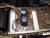
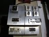
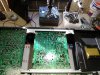
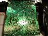
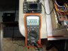
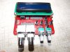
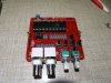
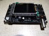
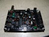
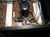
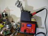
I've been following along because I have an SA-828 too. It used to work fine and then one day I turned it on and the right side was all static mixed in with intermittent audio. Then it stopped coming on at all. : ( I'm sending along a few photos to show where I am so far, (with your help, of course) I have tested all the parts you see and they all test good. I have also tested all of the diodes and they test good too. I am kind of at a loss as to my next move. I thought sure I would have found the bad part by now. I hope you guys will get back to work on yours soon so I might learn something about my stereo because I love this thing and I really miss it. If anyone has any ideas feel free to let me know PLEASE!!! Thanks again for all your help. I really appreciate it
 

Attachments

  • GEDC2888.JPG
    GEDC2888.JPG
    324.7 KB · Views: 103
  • GEDC2894.JPG
    GEDC2894.JPG
    209.5 KB · Views: 127
  • GEDC2895.JPG
    GEDC2895.JPG
    364.9 KB · Views: 113
  • GEDC2891.JPG
    GEDC2891.JPG
    348.2 KB · Views: 138
Welcome to EP @darryl603
If I understand correctly you have one Good Left channel and one Bad right channel before removing parts?
I see you removed parts from the good channel and common parts(like the bridge rectifier,this makes no sense to me.
Removing parts for testing isn't normally necessary ,unless they are suspicious when testing them in circuit.
Did you mark which part was remove from which place and which channel?
If you didn't ,adjusting of both channels needs to be done.

Can you please put-up a list of the devices you have tested so far with the test values?

What test equipment do you have? DMM, Scope etc.?
 
I have a digital multi meter and a cheap dso138 oscilloscope and signal generator I bought and put together...
 

Attachments

  • GEDC2896.JPG
    GEDC2896.JPG
    245.6 KB · Views: 106
  • GEDC2376.JPG
    GEDC2376.JPG
    305.5 KB · Views: 104
  • GEDC2379.JPG
    GEDC2379.JPG
    289.1 KB · Views: 119
  • GEDC2380.JPG
    GEDC2380.JPG
    291.6 KB · Views: 160
  • GEDC2382.JPG
    GEDC2382.JPG
    352 KB · Views: 97
Last edited:
Welcome to EP @darryl603
If I understand correctly you have one Good Left channel and one Bad right channel before removing parts?
I see you removed parts from the good channel and common parts(like the bridge rectifier,this makes no sense to me.
Removing parts for testing isn't normally necessary ,unless they are suspicious when testing them in circuit.
Did you mark which part was remove from which place and which channel?
If you didn't ,adjusting of both channels needs to be done.

Can you please put-up a list of the devices you have tested so far with the test values?

What test equipment do you have? DMM, Scope etc.?

The stereo did work for a while with the one channel good and the other one sounding distorted and then the relay quit switching on altogether I have not removed the output transistors from the heatsinks so they can only go back in where thay came from. Everything tested good ...


NPN --- PNP

BE - .5 - OL

BC - .5 - OL

EB - OL - .5

CB - OL - .5

CE - OL - OL
 
Last edited:
I was testing resistors last night and I came across R689, R690. Both are 10^ 1W but I was measuring 0.000 on both of them. There are a couple other 10^ resistors there too and they measure fine. Does the coil L601, L602 beside R689 and R690 have an effect on the readings I'm getting for those two resistors?
I guess I should pull those too : )
 

Attachments

  • GEDC2900.JPG
    GEDC2900.JPG
    252.8 KB · Views: 87
It is nice that you have a DMM and scope,they will both be very handy.

The problem with the Tr's you have pulled out is with the TO-220 types ,
those that are on the L-shaped heat-sink.
Unless you have marked which channel they came from(did you) you will need to adjust both channels !

Yes L601,L602 are 0ohm resistance in DC(practically shorting R689/R670).
Please don't pull out any devices devices for testing for now.

How did the bridge test?


So,the problems are:
1. Output relay not clicking (no sound from both channels).
2. Bad right channel(deteriorated from noisy/intermittent to no audio at all) .
 
I have a digital multi meter and a cheap dso138 oscilloscope and signal generator I bought and put together...
It is nice that you have a DMM and scope,they will both be very handy.

The problem with the Tr's you have pulled out is with the TO-220 types ,
those that are on the L-shaped heat-sink.
Unless you have marked which channel they came from(did you) you will need to adjust both channels !

Yes L601,L602 are 0ohm resistance in DC(practically shorting R689/R670).
Please don't pull out any devices devices for testing for now.

How did the bridge test?


So,the problems are:
1. Output relay not clicking (no sound from both channels).
2. Bad right channel(deteriorated from noisy/intermittent to no audio at all) .

Correct no power good relay and when the right channel did work, it was distorted.

On the rectifier, I held the negative lead on the notched end and positive moving clockwise, I got .507, .911, .484

We can bias the output, that shouldn't be a problem
 

Attachments

  • GEDC2902.JPG
    GEDC2902.JPG
    206.2 KB · Views: 85
It is nice that you have a DMM and scope,they will both be very handy.

The problem with the Tr's you have pulled out is with the TO-220 types ,
those that are on the L-shaped heat-sink.
Unless you have marked which channel they came from(did you) you will need to adjust both channels !

Yes L601,L602 are 0ohm resistance in DC(practically shorting R689/R670).
Please don't pull out any devices devices for testing for now.

How did the bridge test?


So,the problems are:
1. Output relay not clicking (no sound from both channels).
2. Bad right channel(deteriorated from noisy/intermittent to no audio at all) .

As for those TQ-220's Don't forget, I have a 50% chance of putting them back the way they were. : )
 
It is actually 25% ....but even 50% means re-adjustment is a must !

About the bridge testing:
The way you did it is partial .
You need 8 measurements to test it properly ,2 for each diode.

KBPC606-image.jpg
 
No, 0.9 is a reading of 2 diodes in series ,this is not the way to test properly.
You should test each individual diode twice reversing polarity.
You should get : about (0.5-0.6) and O.L for each diode.
 
No, 0.9 is a reading of 2 diodes in series ,this is not the way to test properly.
You should test each individual diode twice reversing polarity.
You should get : about (0.5-0.6) and O.L for each diode.

Right I rechecked each individual diode forward and reverse and read roughly.485 forward and ol reverse so I assume the rectifier is working properly.

I also checked Q703, Q704, Q708, Q711 and they all check good.
 
Last edited:
I tried to put the schematics all on one page which works okay but the scans were missing some areas so I couldn't match them up perfectly. But at least I don't have to keep swapping them out so much. It's 4 meg so I couldn't upload it. If you want to take a look, I could email it to you...send me a note to [email protected] it's a jpeg I cleaned it up and sharpened it a bit.
 
Last edited:
Yes the bridge is fine.

What you should do is assemble back all parts removed.

Disconnect all speakers from the unit. disconnect all inputs from the unit.
Then power it up,and put the volume at minimum.
Does the relay click?

At this stage we can do some voltage measurements in order to locate the fault.
 
All back together! Same result as before : ( I expected that though because I didn't find anything wrong. At least I know all those transistors are good. The display seems to be fine. What do you think?
 
Please measure the DC voltages relative to chaises GND on IC1002 (TA7317 ) it is a SIP 9 pin device.
And both sides of D1001 relative to chaises GND .
 
Thanks for helping me. I really appreciate it. What do you think about pin 6?
D1001 -38.1 v + 39.4 v
IC1002

1. .648 v
2. -.737 v
3. 0
4. 0
5. -347 mv
6. 37.8 v
7. 0
8. -27.7 mv
9. 2.84 v
 
Last edited:
Top