.Sir adamdavies986 . . . . . . . . the 1st
If you were able to fry one of those units, then I guess that unit doesnt have as good of a thermal shutdown and cutoff /protective features as its old grandfather 1875 series did.
I usually just like to refer to application notes from the IC manufacturer, where they have built up test prototype units , and I then just use their PCB layouts . . . . seems like Philips made none and since being acquired by NXP as their new Daddy Warbucks, he is certainly going to worry about the past.
Probably more likely he is going to declare . . . . Not For New Design. . . . . and quantum leap shift to present audio Class D digital design technology.
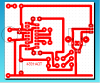
Here is a
MORE direct foil layout path of a TDA 1554Q build . . . . . . that has been around since ~ 2011.
I only question its smaller foil eyelets draw in choices , making the necessity of dressing some component wire lead length along and coincident with the adjunct foil path.
Also I would shoot the rear speaker output leads straight back . . . . enough to clear the heat sink fins.
That would then leave that further back foil area, a to build your regulator and USB connector on.
FULL REFERENCING at . . . . .
HOT LINK https://3shared.wordpress.com/2011/08/12/tda1554q-22w22w-bridged-chip-amp/
PCB FOIL SNIPPET . . . . .
73s de Edd