Maker Pro
Maker Pro

Storz & Bickel Plenty Vaporizer Circuit Repair

Hello EP Forums,

I found this hub while trying to fix my device. I'm looking to see if I can get some community advice so that I can keep from throwing another perfectly serviceable appliance in the trash. I've tinkered with electronics all my life, starting with my TV Antenna when I was a kid, eventually graduating to my computer. I've no education beyond HS physics though. Really the most I think I understand is simple circuits. Recently I replaced a bimetal thermostat on a space heater that suddenly stopped working. Successfully. Today however, I am out of my league. So, I am hoping to enlist your help. Here goes:

THE DEVICE/APPLIANCE

It’s a Storz and Bickel vaporizer. Basically, a heating element that allows a user to designate an upper temperature using a dial. While the device is heating, a little light bulb that turns on indicating the device is warming up. Once the device has reached the desired ‘heat level’ selected through the dial, the device has a thermostat that opens the circuit inside the device so that the heating element stops receiving current (stops heating up; an auto-off feature basically). When the circuit opens, the little bulb also turns off as well. If the user should choose to activate (close the circuit) the vaporizer again, one simply pulls a trigger on the device that trips some mechanism that closes the circuit to reactivate the heating element which then shuts off (again) at whatever upper temperature is selected. You get the idea. The device also has a switch to turn it on/off.

THE MISTAKE

I’ve owned this device for almost six years and it works great. I never had a reason to open it up. Until recently I spilled some juice on it, I opened it up to clean it, and once I put it back together it started acting funny: when I would turn the device on, it would heat up to the desired temperature no problem. Now however, once the temperature dropped and I pulled the trigger, the light would turn on for a moment, then off, then on, then off, like it was trying to heat up to the selected temp but had trouble. Initially I though perhaps I had accidentally moved a wire or something too close to the thermostat sensor and now the heating element was tripping up the thermostat. But then I realized it was just the light bulb had a faulty connection. Unfortunately, too much tinkering led to breaking the light bulb wiring.


THE PROBLEM

Thinking it was just a little light bulb with a simple circuit. I figured, oh well, I’ll just forgo the bulb and close the circuit by cutting out the bulb and splicing the wires leading in and out of the bulb. When I turned the device on for a half second, all the lights in my house went off for also a half second. Clearly not the correct course of action. So I took to more investigating.

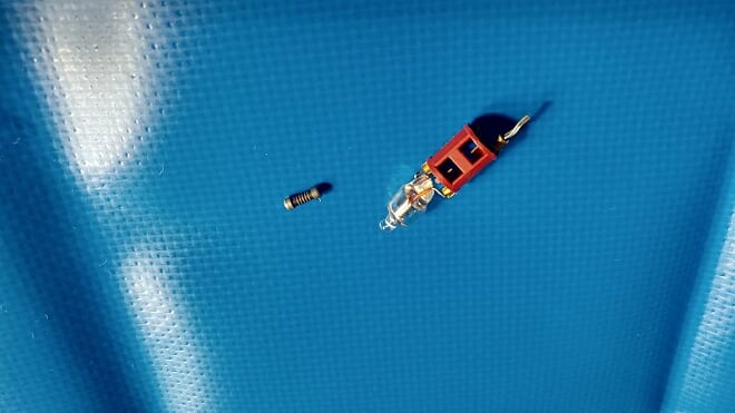
When I took apart the bulb, I noticed it is connected to a little chamber that has some tiny little battery looking thing (a resistor? diode?) that can be removed from this crimson colored housing. It has a grey/shite spiral marking. The bulb and crimson housing with tiny battery were all encased in another piece of white plastic that had some markings on it (???, 128V, 180°C, ???). I could not make the first and last parts out. The first part looks like the number 200 or it could be 20Ω but that’s pure conjecture, it really is too blurry to tell.

Anyway, that’s the issue. I’m hoping to get some input from anyone who can help me identify the parts that I need to replace so that I can fix this (what is this crimson housing called, is it sold at stores?). Or if these are custom parts, offer me a solution that I could rig so that the device works again (even without the lightbulb), safely. Ideally, I would like it to work as intended, with lightbulb and all. Check out the pictures below. If you have any suggestions or questions. I’ll check back to reply. Thanks strangers!
y4mlqm60sHU-YKNSPBDCncu5BV3SS-JfvvYn9rYxYRdgBnPQhsMsmk00BJuAIbcyupzWkEGvMDlWb9taxpBukyljPHPl4mtWH1UmlkfrGmwNZkm8v2NCzJX-KWtK4vn3pjrrm_4b1R7wZlEY0-CWEy4ZgEdTBf7RmbqGLpR-SIgxfJGt9Alk6WjABwWFBbiHaFs6B99uXQRYXCeq1nBxnWS4w


y4mY9yVf7ak2muLrDvqJvsMTQXcFqvv7QVUk_O5SG99lVOAcQW4Rs9NQAIE3KW_YHRt99VYLHt90TlirMCVLCKca3QnD0v_KRNUB7crkUN5Z3H4p17cJ2Uze2Ei1i7M_GbDWtzyaKosP4aARerFOTSNTwwu12DTyN_rL_iog5qDBf7efG35NW7ppKBDIGKEuHvvpx5GmRuYkyV0wY3H0iY_Ow


y4m3kGdiD8EQcblA5K5kqPnChPou9psFwPi_QsuQErbrcOAwVgd3WdTtQkwnebYfQ05tVU8fMV8esUDBpQgBaxQQaC7ai-S9s14jLxqVWp_TzIZL8TOfAn_o-xSiV-LXgmjkj8ISc2ae_dcLnf4EQR6IzulWQ66zvp-sxn2h4mBjuwWXReL1VTbgClvfGsLjLfiQev8O64FZe1Hwf1uKq72iw


y4mqdDC2ZIB5X5tR-h4flKOTs_pEw0-AB2H3Ecupyzjk9mSIsXUawmeQOJPOBDQG8Ku7FgoyAS_jwGvZM-gUPxfpTLM-eAKmZUkQ4E92g9lkxudG0SBIdLo4th06TEp9JFIRny1dBpsjOr3bTpdBNuskT822dqUP82bdtmuF2M2Lx0meAPD4yfgFytfQcxCRiI6qa6Cp6y-kITtJa5oje72Mg


y4mcJG2RAYZ7A32Gbsk4iNI-mdnJ3EiNxYWmDakfdYQwwAdhIv7M4WErMnhb44v_7ZymWcOMjmrTH-cGRE-sNZZ2E4reISO8V_KjD83oedP3tf4Tke9uAUFwdbL1Py3Qnx56YAQRM32mF4xPBJSTrU76vzF2Dm385hst8vLc9-IJbsFGyyq2IMNEMuOQE8NpWfFuG3umR8Im2Hfa_rX43Q5Ig
 
Last edited:
Sir Chipmaker . . . .

WOW . . .250-300 for that unit !

You seem to have your self a stubby NE-2 typish of neon lamp along with its required series dropping resistor at the left, in order to operate from either 120 or 220 VAC . . .where is you ?

Depending on the neon lamp -
High-brighness NE2H lamps use 22k-33k in series for 120v
Normal brightness NE2 use 120K-220K for 120v use.
Double the resistance value if you happen to be in a 220ish volts AC supply situation

It is being wired across the heating element in the unit to indicate when FULL AC power is being introduced to the heating unit by an adjustable series inserted electromechanical thermostat.
With you placing a dead short directly across the heater element . . .CONGRATULATIONS . . . . one then should fully expect the thermostat contacts to now be solidly spot welded together during that duration until the house breaker tripped OR an intenal fuse / thermal cut out opened up.
Time to see if the company sells replacement repair parts .

You say . . . .
When I took apart the bulb, I noticed it is connected to a little chamber that has some tiny little battery looking thing (a resistor? diode?) that can be removed from this crimson colored housing. It has a grey/shite spiral marking. The bulb and crimson housing with tiny battery were all encased in another piece of white plastic that had some markings on it (???, 128V, 180°C, ???). I could not make the first and last parts out. The first part looks like the number 200 or it could be 20Ω but that’s pure conjecture, it really is too blurry to tell.

Note the thermal cut out ( battery) below , and it should be mechanically mounted /kissing the sampled temperate device
upload_2020-6-28_15-8-18.png


Thassssssssiiit

Aside . . . .
Considering your actions with this unit . . . .I'm wondering if your earlier excursions into Tee Wee Antenna design, might have involved either bed springs or coat hanger wires ?

73's de Edd . . . . .


Just when you think you've won the rat race . . . . BAMMMMM . . . . . then along come faster rats.


.
 
Last edited:
Sir Chipmaker . . . .

WOW . . .250-300 for that unit !

You seem to have your self a stubby NE-2 typish of neon lamp along with its required series dropping resistor at the left, in order to operate from either 120 or 220 VAC . . .where is you ?


It is being wired across the heating element in the unit to indicate when FULL AC power is being introduced to the heating unit by an adjustable series inserted electromechanical thermostat.
.

Hi,
Thanks for the input. I'm in California and yes, I'm pretty sure it is being wired across the heating element in the unit to indicate FULL AC.
I took that splice out and the switch indicator still receives current but no way of knowing yet whether I irreparably damaged the device. The lights in my house did not actually stay off, they just flickered. I did not smell anything burnt from the device. So I am hoping this is still salvageable. Any hope...?
 
Just try it and see if the unit still cuts off upon reaching set temp . . . . .you just won't have the neon as a visual indicator now. Possibly use a meter set to 250VAC and clipped into circuit where the lamp was connected.
 
Hmm,
Well, the circuit is open right now (I took out the splice) because the bulb is gone and the wires leading in and out of it are not connected to anything. Before I had done the splice, when the light bulb was still connected but broken (only one terminal wire connected), the switch (which has its own light) light would come on but the heating element would not work. Presumably because the bulb is part of the whole device circuit, so when the circuit is open, the heating element won't work. I want to close the circuit but simply splicing is not the way to go. How can I put something in place of the bulb that would properly close the circuit without a light? Should I just run resistor when I splice? I have no clue what I'm doing. All the help is appreciated.
 
Would it work to just clip the resistor housing away from the lamp and re-create the scheme? What variety of resistor could/should i buy?
 
Thir Chipmaker . . . . (Whassamattahyou? never heard anyone wif a lisp ? )

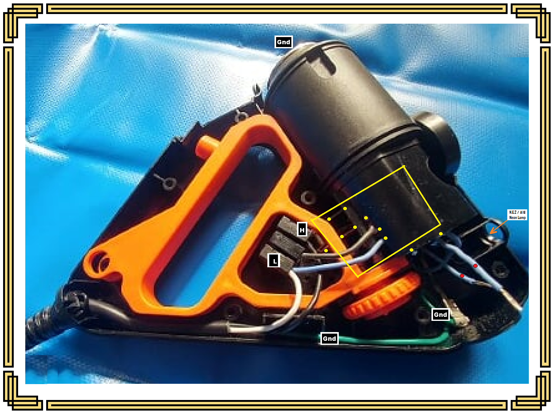
If you refer to the first photo below , I am placing all of the markups that I seem to be able to confirm.
The AC power connections and their standardized wire colors are going up to the three BLACK terminals, where they then end.
After that, then its being their own helter -skelter choice of wiring color coding.
The GREEN safety ground wire at the bottom should go to any externally exposed metal that can be touched on the unit.
e.g. . . . . .
I only see the vape elements Stainless Steel holder ( at the very top of the pic) and . . . the unshown . . . . flexi metal hooka pipe that twists around in a spiral and then extends afar on upwards from that area... .looking for a set of lips.

My YELLOW boxed area and all of the YELLOW dot areas are needing a hands on examination . . . ergo . . .that I no can do.
I am " consuming " that the two RED dotted blue wires were / are the connections into the Neon indicator lamp and its series resistor that you have now torn down.
That whole assembly, was once nestled down within the ORANGE arrows area cavity.
Last relevance to this photo, is being the orange temp adj knob, which must be mechanically adjusting one of the electrical contacts, as shown, by altering spacing on the fixed contact of the bi-metallic warp thermostat. Its action is being totally hidden away from my viewing.

Refer now to the final combo schematic / mechanical drawing of the perceived wiring connections of this unit . . . . .

Same H L and GND connections are being shown on the left side of this drawing.

If it has a MAIN POWER switch it must be inserted into the HOT AC line input where I have the BLACK X's showing
If the power switch is closed, then power passes down to the left contact of the bimetallic thermostat.
If the Temp Adjustment screw is not pressing down at the GREEN triangle contact area, it is being at its lowest temp setting and power passes thru he two closed contacts on to the one shot thermal cut out.
( Now confirm for me if that unit was being your perceived small " battery " ?)
The power flow continues on thru the heater assembly and finally makes a complete power loop at the L Neutral wire at the end.

Now, at no extra consulting charge, you can see that the neon lamp is being wired right aross the heater unit, so it tells you if / when the heater is being powered up or not, as the unit cycles.
Now we need the bi metallic strip mechanically/ thermally /physically positioned onto or very near the heater element.
Also, that thermal cut out needs the same mounting situation, wherein its internals melts at . . . .I believe that you found 180 deg C written upon it . . . .and it is then being an opened electrical circuit . . .FOREVER..*****

The lower GRAY inset reference relates to the electro-mechanico action, when the heater gets up to the set temp, and the cojoined disimilar metals strips different coefficients of expansion, will then result in them warping into an arc and thereby moving their associated contact away from the other contact.
Should you have adjusted the temp knob downwards at the GREEN triangle reference, it would have pushed BOTH contacts further downward, so that the warp would have to be even more severe from that position , that results in a longer run time of the heater and a higher upping of the temp before cycling off.
( There are being mechanical enhancements using springs, counterbalances, and even magnetics to create a MORE defined SNAP action in switching . . . . . but this depiction is just showing the rudimentary basics for you.

Now lets look back up to the top where I have drawn in two VIOLET triangles, which I think will coincide with the two RED dots on the bare ended two blue wires of the complete previous photo. . . .confirm that for me.
If you then had the neon and its resistor missing and those wires jumped together that would have the heater shorted across.
Then when you applied AC power, the heater was ignored, but the one shot thermal fuse BLEW just like a regular fuse.
Questionable damage to the thermostat contacts ?

NOW . . .another wiring possibility would be for that thermal fuse to be located further to the right and be between the VIOLET triangle and the heater.
In that wiring situation, a power up, would then have full 120VAC across the bimetallic strip contacts . . .probable spot welding and a tripping of that house lines circuit breaker.

With your only hearing a stutter from the breaker, possibly the first case fits the units wiring hookup.

Now, see what you can find. . . . .with ohmmeter in hand for testing and unit unplugged from house power.
Confirming the suspicioned earlier*****, plus any other possibilities.

WHOLE UNITS PHOTOGRAPHED TEARDOWN . . . . .

VAPORIZER-INTERNALS.png


SUSPICIONED WIRING / SCHEMATIC PATH . . . . .

upload_2020-6-29_3-41-38.png

73's de Edd . . . . .


Question . . . . Where was the toothbrush invented ?
Answer . . . . . In West Virginia . . . . . .
(if it had been invented anywhere else, it would have been called a teeth brush.)


upload_2020-6-29_3-44-31.png
 
Last edited:
Thanks for the detailed attention and explanation. From what I can tell, I think the blue ended cables are actually in the location denoted by these two green dots. I've added some more pictures below. The small 'battery' was actually the resistor attached to the to the neon lamp. I'm not sure if there's a thermal fuse in this device (would it need one?).
upload_2020-6-29_11-11-21.png

I was able to take the original neon lamp and make contact with the wires and the device worked fine without a problem, as well as toggle the auto-off to bring the heater back up to temperature. Tested various times, works fine. I included a picture of the thermostat if you are curious.

I tried to find a neon lamp with a resistor for 120V but no luck. So I decided to get a 220V lamp. Presumably it would still work just shine less bright? I don't know why these don't indicate the resistance on the resistor. Doesn't that have to match? Or is the resistor what makes the lamp 120V vs 220V? There's a formula for this right? Like V = I*R or R = V/I

y4mPITOiigV8veXod0ZvHFp-9FbniOKhug8d4DbY3RfnZGNIeQ21vgJLZZ2rOCN_eD0Exyif0ESYfcAFg4nuKUh5w25RUsUb8ECLyoi5MaG_jfNRnv3OFXorIDqUPUMNKNAy8U94SGINfxYgcl6u9wBLdr6rSs3Mcd7TxlQq130GacYT9PosjEAp1Uc1d-dO-axo8LYggj0xX4xXtf0p6Pt0g


y4mBNVJEKog6hxoVZxWrfOlboXqPiooph7dR106KHoYJlrY-VaY6f0R8xTob_YPVqu2G8qQTOoIDGf1X3NxS50eGhGwuVla2lMTjSp3ywT__cCs2MmAK8AKv3c8p7QGt3NxuUCmOAEzhi7UEZjLrmgz7-OBfGndYzYDynBKGgXklRRemUatYcePSEVMmOKpocAwgATpC8pn8Irh7wL4uzceGw


y4mBTua2R0bze-I9Eimkii5O1ZidC28Sx1XXXa3DBXS04OVrK0labZlDDONFRepBVGdHOd9ddxfoJhtQbW0RrRWQeVXe8qqqxCMN_2-cqBL_bFysS_1L0TLLxe1Ud4weNU0Zbe82HGlj4x3OAVEXPlOK555l1WUB5l3b9Z6sTksGtlubIG-rgZQcOmLJX6cLYVBY5Dgn2UGeuitYka_oepFSA
 
Sir Chipmaker. . . . . . . ( no speech impediments today) . . . . nevernosomewhathowsoever . . . .Hmmmmm . . .Chipmaker . . . . COW or Solid State ?

Now yer' talkin' . . . . wish that I could had that definitive of a photo back at the get go.
And on it, you can see just a minor portion of the bimetallic warp strip and its conjunct, arc tensioned cantilever phospor bronze spring that gives a sharp transitional snap action.That, along with the end mounted ceramic rod associated with a cycle reset or when making a temp change.

As per your "shorty" A1D neon indicator lamp and its series current limiting resistance value.
Refer back deep into to your cranio-neural-cortex long time memory state and think of the lamps brilliance prior to having any problems onset.
You just need to install a leaded resistor that equates that prior resistance.Seems like you were suggestuve of reading a " two
" value of resistance being involved, as it is, I am only seeing the spiral bands of a naked carbon film resistor.
"Two" could relate to a 22k or 27 k resistor which are within the parameters of resistance which I initially gave you.
In the interim, my memory was jogged from only remembering classic NE-2 lamp number for 70 years . . . . and then, the newer "stubby" A1 series of lamps.

If you are being an active electronics "DOER ! " you should have a cache of old cast off / donated or curb find electronics that would yield donor resistors , or parts galore, within your needed range.
Just try values within the 20K ohms or upwards spectrum, in order to see what gets your original brightness of lamp illumination.
You DO have a DVM with ohmmeter functions . . . .don't you ?

BUT . . . examining your very bottom photo, it seems that if that is being the original resistor, it is still good and produces what seems to be a bright enough light.
Also, the A1 series of lamps have options of different gas fills for different produced colors.
Each gas used in filling a . . . . "neon" . . ." wink-wink" . . . light has its own color. Neon is reddish- orange , helium is orange, argon is lavender, krypton is gray or green, mercury vapor is light blue, and xenon is gray or blue. Mixing gases and elements added to a "neon" light creates different hues.

Yours appear to me to be yellow, so they may have added an additional internal phospor coating that can provide even other colors as electron bombardments light them up.
I even remember ones producing white colored light.


Thaaaaaaaaaaaaaaaaassit . . . . . .


73's de Edd . . . . .

I already KNOW the speed of light . . . .so, now, can we start figuring out the speed of dark? . . . and it also must be quite impressive . . . .what with my perfunctory initial experiments in turning off the porch light . . . and then RUSHING outside to check !


.
 
I have owned two Plenty vaporizers and both had the same issue after a few years of use. They heat up fine the first time, but will not heat to full temperature the second time after being hot. I used a volt meter to verify the thermostat and switch were passing voltage properly when it is malfunctioning, so I assume it is the themal fuse causing the problem.
 
Last edited:
Sir Kurt . . . . .

so I assume it is the themal fuse causing the problem.
If you are getting any level of heating, it will NOT be the thermal fuse, with it being bad, the unit will be stone cold dead.

PARTE DEUX . . . . relying solely upon the infomational aspects of . . . .

both had the same issue after a few years of use
et
They heat up fine the first time, but will not heat to full temperature the second time after being hot.

I interpret that as . . . after all of the years of time of use, is NOT being related to the temperature that the unit reached at purchase day one , versus the temp that the unit reaches at this current day and time time.
BUT . . . . that at THIS dates time of use . . . that the temp that the unit reaches on its first load of fill water . .versus . . . the temp that the FOLLOWING second load of fill water . . . does no seem to equate.

Now mind you . . . . that I am blind deaf and dumb on this end from any inspecting of that unit, but can expect its water storage container / heater core to be constructed of either alum-a-ninny-yum-yum if being an el cheapo unit . . . . or . . .stainless steel if being a pwemium bwewed unit.

Next one would expect the OUTER center bottom of that container either being spot welded or compresssive coupled /clamped to the thermostat for temp sensing transferral.

Back on day one the containers INSIDE bottom was being pristine clean metal.
With years of use, a lime/calcimated insulative layer would deposit and build up in the bottom
of the container.
Your first run of water would be into a cold unit and its container conduction aspect to the thermostat would take "X" time.
Your next fill would be into to a warmed / warmer container and the isolation between the water and the themostat sampling point would now have a slightly EXPANDED lime/calcium layer inhibiting the same thermal water temp sensing reference base . . . . . . as also would your 3rd or ---->fills also.

This then relates to a longer heat run on the stone cold unit, as then being compared to all of the the subsequent "warmed" up runs.


If visible / accessible see if there is not a scale build up now being at the bottom, as is suspicioned.
Use hot vinegar or one of the many touted commercial scale deposit cleaner uppers to get the bottom back to bare metal.
Thaaaaaaaaaaasssssit . . . . . . .


jogged . . . . as an aside remembrance . . . . .
I had done wented and plumb fergotted, this a here post . . . but seems like everybodies done got ther FULL nickels werth from it !

73's de Edd . . . . .

Progress is made by . . . . . lazy men . . . . . looking for an easier way to do things.


Last edited:
ADDENDA . . . .
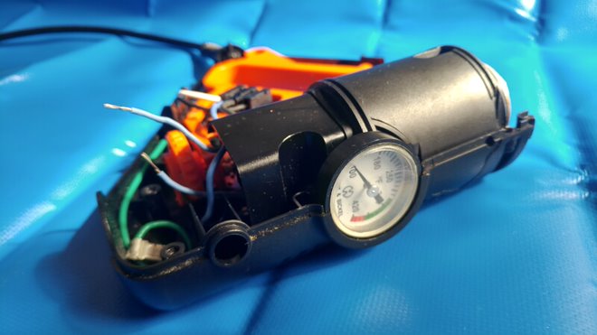
Considering the small size of this unit and its handle aspect . . . AND a TEMP gauge ?
th

its not being my expected conventional water vaporizor . . .but an electrified HOOKAH !
I hold the same suspicions of an isolative / thermally insulative build up still being at the bottom of the unit, but from dried and caked vaping fluids.
With use of 409 cleaner / solvents /brushes/ gentle scraping, being the modes of removing of that build up.
BEING 1000% SURE . . .that NO toxic solvent traces remain . .if so used.
 
Last edited:
A. Is the thermal protection mounted near the heat element. When I bypass this, it works perfectly again.

B. Is the adjustable thermostat which works fine.

By the way, it is a great unit. I highly recommend it. The company honored my three year warranty and replaced the first one. I have had this one past the warranty.
 

bertus

Moderator
Hello,

I would never bypass a thermal protection.
When it is bypassed and the thermostat fails short, a fire will likely happen.

Bertus
 
A. Is the thermal protection that is going bad. I don't want to leave it bypassed due to the fire hazzard, so I might clean it, or replace it with a thermal fuse that blows at about 450 F.
 

Attachments

  • 1114201615a-2.jpg
    1114201615a-2.jpg
    131.6 KB · Views: 31
Hi there
Does anybody know the specs or some compatible thermal protection?
I found this looks pretty close but 200c is maybe too low?
https://chefglobal.es/en/bi-metal-t...e-faston-63mm-vertical-ego-franke-salvis.html
The detail's are on the side of the thermal fuse, i searched them and found a company in germany that make the exactly fuse l. I ordered 2 but havent fitted 1 yet as it will require a little mod as they are slightly different fitting. ive currently removed the fuse and the thermostat is working fine atm, that fuse is a real weakness in the design. running great without it, but will fit one at somepoint.
 
Last edited:

Similar threads

Top