Hi
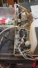
I am trying to repair a sterilizer. It has 3 basic components that run on 115 vac. I do not have a schematic, and cannot get one. There is a water pump thatI looked up is run by 110 vac, a solenoid that runs from 24 vac, and a small heater 110 vac. And a compressor 110 VAC.
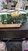
110VAC goes into the one main circuit board, then appears to be switched on and off by signals when required. Measuring the heater, compressor, solenoid lines with probes across I get no voltage, when the component turns on I get the 115 VAC, which seems normal. The water pump when off has 115 VAC, when it turns on to run it goes to 154 VAC. Also to note if I read across the lines of the pump I get 154 volt D.C., and it drops when the pump is triggered on. Lastly when I put a DMM lead on one side of the lines at the pump it reads 115 VAC without attaching the second lead?
The heater, compressor, solenoid all seem to measure correctly in my opinion, the water pump seems to have an issue. I also used an Oscope on the water pump lines to see if could see a D.C. wave but the sine wave appears normal and 60HZ. Also to note the oscope says 330VAC, and when the pump switches on, the reading changes to 115VAC with probes across the lines.
Any ideas of which components may make these type of readings? Thank you
I am trying to repair a sterilizer. It has 3 basic components that run on 115 vac. I do not have a schematic, and cannot get one. There is a water pump thatI looked up is run by 110 vac, a solenoid that runs from 24 vac, and a small heater 110 vac. And a compressor 110 VAC.
110VAC goes into the one main circuit board, then appears to be switched on and off by signals when required. Measuring the heater, compressor, solenoid lines with probes across I get no voltage, when the component turns on I get the 115 VAC, which seems normal. The water pump when off has 115 VAC, when it turns on to run it goes to 154 VAC. Also to note if I read across the lines of the pump I get 154 volt D.C., and it drops when the pump is triggered on. Lastly when I put a DMM lead on one side of the lines at the pump it reads 115 VAC without attaching the second lead?
The heater, compressor, solenoid all seem to measure correctly in my opinion, the water pump seems to have an issue. I also used an Oscope on the water pump lines to see if could see a D.C. wave but the sine wave appears normal and 60HZ. Also to note the oscope says 330VAC, and when the pump switches on, the reading changes to 115VAC with probes across the lines.
Any ideas of which components may make these type of readings? Thank you