Maker Pro
Maker Pro

Stepper motor or Servo?

Hi,
To say I'm new to electronics is an understatement! I have very very basic knowledge - my background is more mechanical and in high pressure pumps, but I want to make a device that requires some electronics. I hope you guys don't think my questions are too trivial! The answer might be obvious, and I hope it is, but it's out of my comfort zone. That said, I've been keen to learn some electronics for a while, especially as nearly everything contains something electronic these days.
Basically, I need to have a wheel that when prompted, turns through a very specific degree of rotation and stops until it receives the next instruction to turn. Each movement must be 1/17th of one full rotation, which I calculate to be 21.18 degrees. This is vital because the wheel will be divided into 17 sections and I don't want it to become misaligned over time. So my questions are;

A) Would I use a stepper motor or a servo?

There is no real weight to the wheel - think of it as being similar to a hamster wheel (except it lays horizontally) made from Acrylic, approx 110mm in diameter and 30mm in depth. It carries no imposed load, I simply have to turn the wheel by the exact increment, job done. The speed it turns would be inconsequential, but relatively slowly would be better I guess.

B) Do I use some kind of sensor / microswitch to stop at precisely 21.18 degrees, or maybe a microprocessor?

I'm already thinking of using an Arduino or Raspberry and a motor shield, because I also want to be able to activate it remotely via the interweb and therefore need it to talk to the modem nearby. I believe this is done with an Ethernet shield? I guess I'll sort through that problem in a different blog once I've sorted out how this wheel will actually operate?

So, thank you for your time and patience. I really hope some of you nice people can throw some light on this for me!

Cheers.
 
Do you need to keep it in position, IOW is there any load imposed that may make it turn off posn?
Although a stepper motor has a natural indent, without gearing it indexes 1.8° a small DC motor with a fairly high gearbox ratio would have quite high resistance to back feeding at rest.
One down side to this is you would need some method of stopping at each index, a limit switch at each location, you could use just one on the wheel itself, but then the problem of how to commutate the L.S. conductors out, Unless it only turns 1 revolution and then reverses?
M.
 
I just remembered one method I have used in the past quite successfully to bring power out of a slow turning wheel, was to use a 1/4" phone plug and jack, the jack was mounted to the base and the 1/4" mono plug was used as a pivot on the wheel. .
M.
s-l1600.jpg
 
Last edited:
Thanks for you replies so far guys.
I initially thought of using a simple dc motor and worm gear set-up to prevent the wheel turning the motor and shifting out of position. Gearing could also be used to help get the correct amount of rotation through consideration of the ratios. However, I believe these motors are difficult to stop accurately? Or perhaps at the ratios I would use (the wheel can turn slowly), the motor would stop quickly enough to stay aligned, as you indicate Minder. I started to look at steppers because I thought it was possible to calculate the 'run time' as they operate incrementally, which could then be programmed into the Arduino (which will be installed anyway to control other aspects of the device). But I have taken on Minders information about the 1.8 degree index of stepper motors, thus meaning I would have to use gearing anyway, as Colin said. So if I use a 17:1 reduction on a stepper motor, in my mind I'm still left with the original question - how do I stop the motor precisely after each revolution?
As I'm writing, I'm wondering whether to just use the dc motor / worm gear set up and use something like a reed switch and magnets set at each stop position, then work out how to program the board for this? Or even still use a stepper motor with this set up?
 
Things to consider, a stepper motor operates to fixed increments, a servo motor with its PID requirement, could require too much involvement, programably speaking.
If you find a DC motor with the maximum reduction that will still give you the required rpm, then this may be a good choice, you can either use the single switch arrangement I mentioned or multi switch with an actuator at each of 17 positions, this would not require much in the way of µp power, more discrete hard wired system.
How do you intend driving the wheel? i.e. direct? belt or?
M.
 
If you use a reed switch, it is not likely to be very accurate.
A 1.8deg stepper will have 200 steps per revolution or 11.76 steps per position. You could round up to 12 steps and insert some 11 steps.

What accuracy do you want?
 
Any method you use that does not involve feedback will get out of sync eventually. Even stepper motors have to be calibrated each time the power comes on. Think of your ink-jet printer, for example. If it is like any I have owned it whirs like crazy when powered up to sync up all the steppers. If you don't believe me, try turning off the power half way through one of your 17'th of a rotation steps.

An optical sensor under the turntable would work well.


Bob
 
I've used optical switches as Bob suggested and found them to be extremely accurate.
In my application (cam and crankshaft grinders for miniature engines) they repeatedly operate within 1 thou/ inch.
The type are the slot optical switches as found in old printers, scanners etc.
They come as a couple of different types with varying connections but basically contain a transmitter with a built in resistor and an open collector output.
I think your worm drive with a permanent magnet dc motor would a good idea and if you are worried obout over-run then you can always just add a simple relay across the motor for dynamic braking.
I do not see that it would be though as you have very little mass.
 
So a dc motor is the way to go by the sound of it, if I'm following what's being said. With the optical sensor Bob, does this create a beam of some kind that requires points on the wheel to break said beam in order stop the motor? I assume that to move to the next position, the board is programmed to temporarily ignore the broken beam in order to start moving again? This sounds good, as it seems to totally eliminate the need to calibrate or worry about alignment over time. Thanks to all of you guys for your inputs.
To answer other comments;
Duke - it's not so much about accuracy per individual motion, but more a concern about running out of alignment over time and use. Therefore, your suggestion is also a good one, thanks. Running 12 steps a number of times, then eleven would keep things in line too. However, stopping the motor with a suitable sensor seems less complicated.
Minder - I was thinking a direct drive using reduction gearing. In my mind, belts can slip and stretch. But then again, I'm not used to working on items at this scale!
Again, thanks to everyone.
 
Oh, I see more comments while I was typing!
Thanks bluejets, dynamic braking sounds like the ticket. I'm new to electronics, so how would the relay be wired? Just across the poles where the power cables are attached? I assume this would be an easy mod if I find it does over run?
 
Last edited:
I was just looking at the online RS catalogue. There seems to be a few different types o slotted optical sensors - pull-up resistors, phototransistor outputs and so on. Does it matter which one to use?
A permanent magnet motor is a stepper?
 
Found a worm gearmotor at www.motionco.co.uk that runs at just 2 rpm on the output shaft, which is ideal for my needs. If I'm right, it'll take just under 2 seconds to move through the required increment and prevents unwanted movements due to the worm. Along with the suggestion of an optical sensor, I think you guys have helped me pin down what I've got to do. Thanks a million to all!!
If anyone has the time and inclination, would you check out the data sheet to see if it's suitable. The model number is GMW32W1650. Thank you.
 
Last edited:
I was just looking at the online RS catalogue. There seems to be a few different types o slotted optical sensors - pull-up resistors, phototransistor outputs and so on. Does it matter which one to use?
A permanent magnet motor is a stepper?

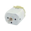
Permanent magnet motor I was referring to just an everyday hobby type dc motor ......apply a battery and it runs, reverse the battery and it runs reverse.

With the slot type sensors, one uses a vane to interrupt the output from the LED and blocks it arriving at the transistor i.e. turning off the transistor and hence the relay (with NPN type sensor)
Will whip up a bit of a circuit later today...bit busy now
 

Attachments

  • dcmotor.JPG
    dcmotor.JPG
    57.3 KB · Views: 77
Just a quick idea...do not know what drives your "request to rotate" (start button) but with a small relay if a micro then simple or if from a 555 astable, simple also.
 

Attachments

  • Example.jpg
    Example.jpg
    160.9 KB · Views: 106
With that type of reduction I would not expect to see any over run or back feed.
The sensors typically consist of a slot that the 'flag' would travel through and break the beam, a LED emitter one side with a photo transistor the other side.
The part number I mentioned earlier has a fairly wide slot allowing a little more tolerance on the alignment.
All you would need is to latch in a relay to apply a momentary start and take it off a position, the next sensor position would release the latched relay, and then repeat for all other posn.
M.
 
Top