Hi swu36,
I can answer that!!!
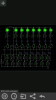
If you look at your circuit board, you will see 5 black three pinned components.
Beside those components are a letter and number. U1, U2, U3 etc.
They are called reference designators and describe what component should be placed there 'ish'.
Q on a board normally means it's a transistor. U normally means a chip.
C a capacitor and R a resistor etc.
So I didn't think U was a transistor. But it can be depending on the software that printed the board.
That's how I see it.
Martin
")