I'm not really a radio amateur, I'm just a guy with a flyback who decided to try making a spark gap transmitter. As you can see from the diagram, it's pretty crude. No LC circuit and the "antenna" is literally the plumbing of the domestic central heating which extends up to about 5 or 6 meters above the transmitter. This advanced contraption transmits on just about every frequency possible but the signal is at its strongest at around 7,45 MHz and reception on other frequencies quickly drops with increasing distance. However, I still don't know what's the maximum range.
So let's go to this thread's main point - the power output. How do I accurately and reliably measure/calculate the power output of this transmitter?
The circuit diagram:
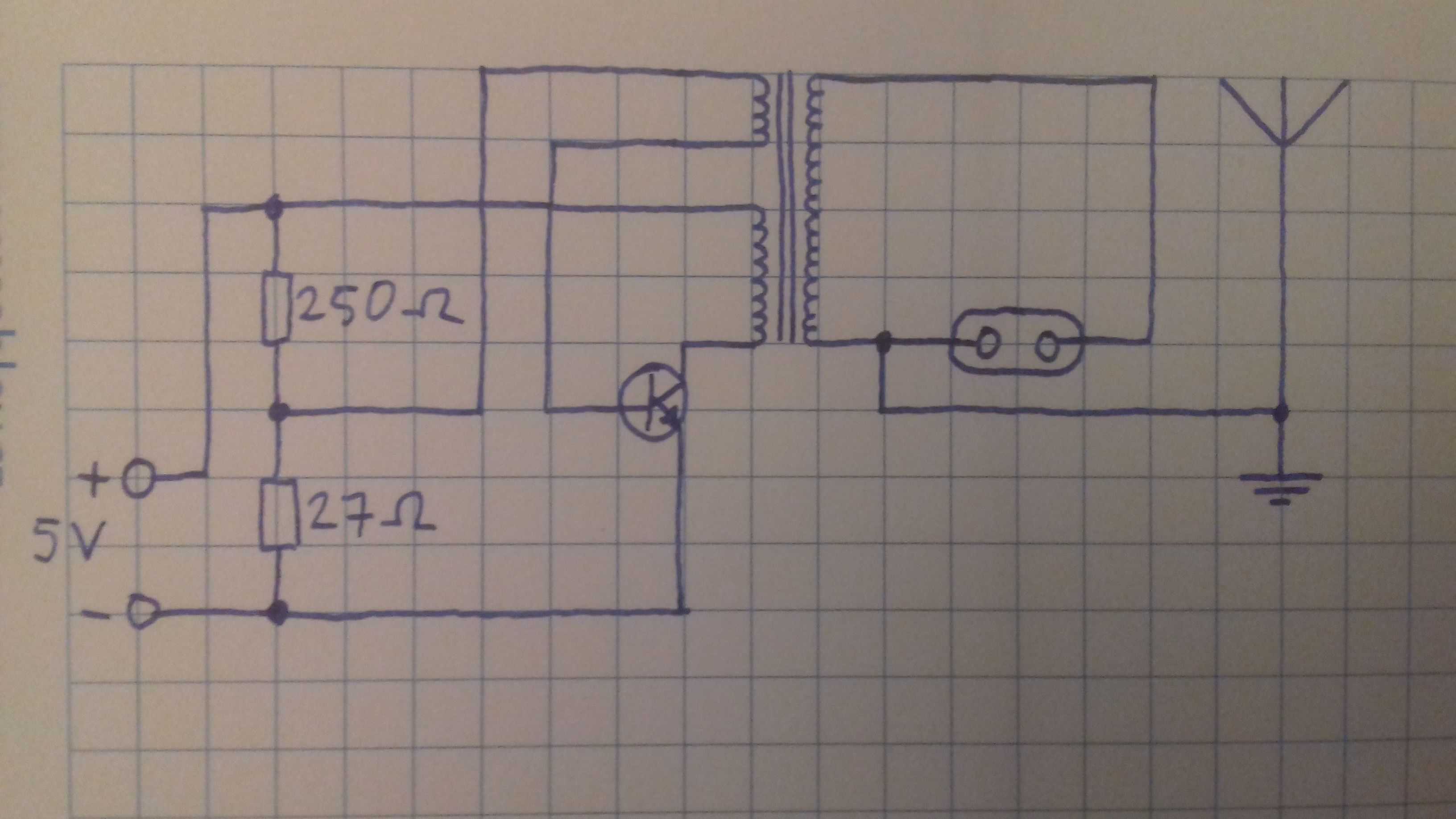
Although not shown in the diagram, there's also a diode right at the beginning for reverse polarity protection. The spark gap is 2,5 mm wide, limiting the output voltage to about 7,5 kV. The maximum voltage it can achieve without such a narow spark gap and with double the input voltage is about 50 to 60 kV.
So let's go to this thread's main point - the power output. How do I accurately and reliably measure/calculate the power output of this transmitter?
The circuit diagram:
Although not shown in the diagram, there's also a diode right at the beginning for reverse polarity protection. The spark gap is 2,5 mm wide, limiting the output voltage to about 7,5 kV. The maximum voltage it can achieve without such a narow spark gap and with double the input voltage is about 50 to 60 kV.