Maker Pro
Maker Pro

Solid-State Switch?

Hi,
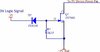
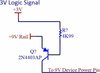
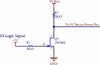
I need to use a 3.0V logic signal to switch a 9.0VDC rail. That is, 3.0V signal = switch is on (closed). Ground level signal = switch is off (open).

The switch can have a max voltage drop of 0.2V. I need to deliver no less than 8.8VDC to my destination (an IC opamp power pin).

IC opamp is only drawing 5mA of current (@8.8VDC). What's the best (cheapest) approach?

Tks, Joshy
 
Or perhaps something like this? The problem I see here is the diode drop across the transistor. I need no less than 8.8V feeding an opamp power supply, and I have a maximum of 9V rail.
 

Attachments

  • BJT Switch.jpg
    BJT Switch.jpg
    28.3 KB · Views: 8

Harald Kapp

Moderator
Moderator
post #6: No. The 2N2007 is an N-channel MOSFET. You cannot do high-side switching (switching the positive 9 V rail) with an NMOS unless you have a gate drive voltage >> 9 V. as it is, any input voltage less than ~ 7 V will turn on the MOSFET, Thus there is no difference between a 0 V control signal or a + 4 V control signal: both are considerably lower than the voltage required to turn the MOSFET off. It will always be on.

post #7: same issue: The base of the transistor is always much lower than the emitter and the transistor will always be on. Besides, a base resistor to limit current is missing.

post #8: will basically work, but the current to the load (device power pin) will be severely limited by the 2k43 resistor. This will work only for very small loads, otherwise the supply voltage to the device will drop way below 9 V and the circuit will not work.

If you really need to switch the high side (+ 9 V) then you'll need a level translator. Here's a good explanation of the why and how. But: Do you really need to switch the +9 V side? Consider switching the low side (0 V). This will also turn off the device but at less effort. A simple switch as shown in our resource can be used.
 
explanation of the why and how[/URL]. But: Do you really need to switch the +9 V side? Consider switching the low side (0 V). This will also turn off the device but at less effort. A simple switch as shown in our resource can be used.

Thanks so much. Yeah, I don't have the luxury to switch ground in and out (like for a relay coil), it has to be +9VDC switched in series for an opamp power pin. It has to mimic a true switch. Very low current, less than 5mA, probably more like 2mA.
 
Very low current, less than 5mA, probably more like 2mA.
An optocoupler plus one resistor will do this. At only 5 mA, the output transistor will be a saturated transistor switch, with less than 0.1 V drop across it.. Choose an optocoupler with a CTR (current transfer ratio) of at least 100%, with a standard transistor output, not a darlington.

ak
 
Top