Let me preface my first post here by clarifying that I am not an electrical engineer of any discipline. I am a mechanical engineer and usually I would use a hammer to fix problems.
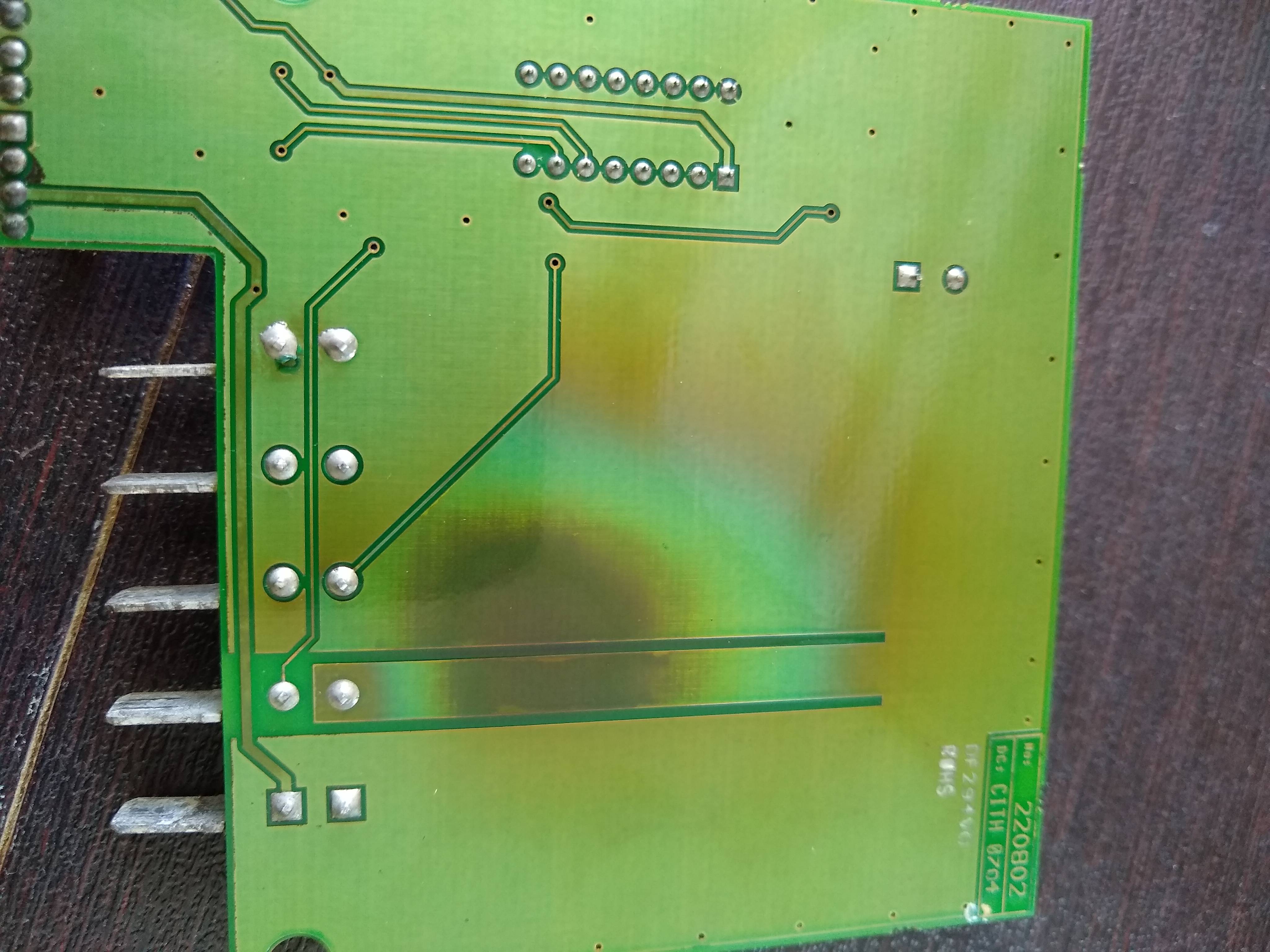
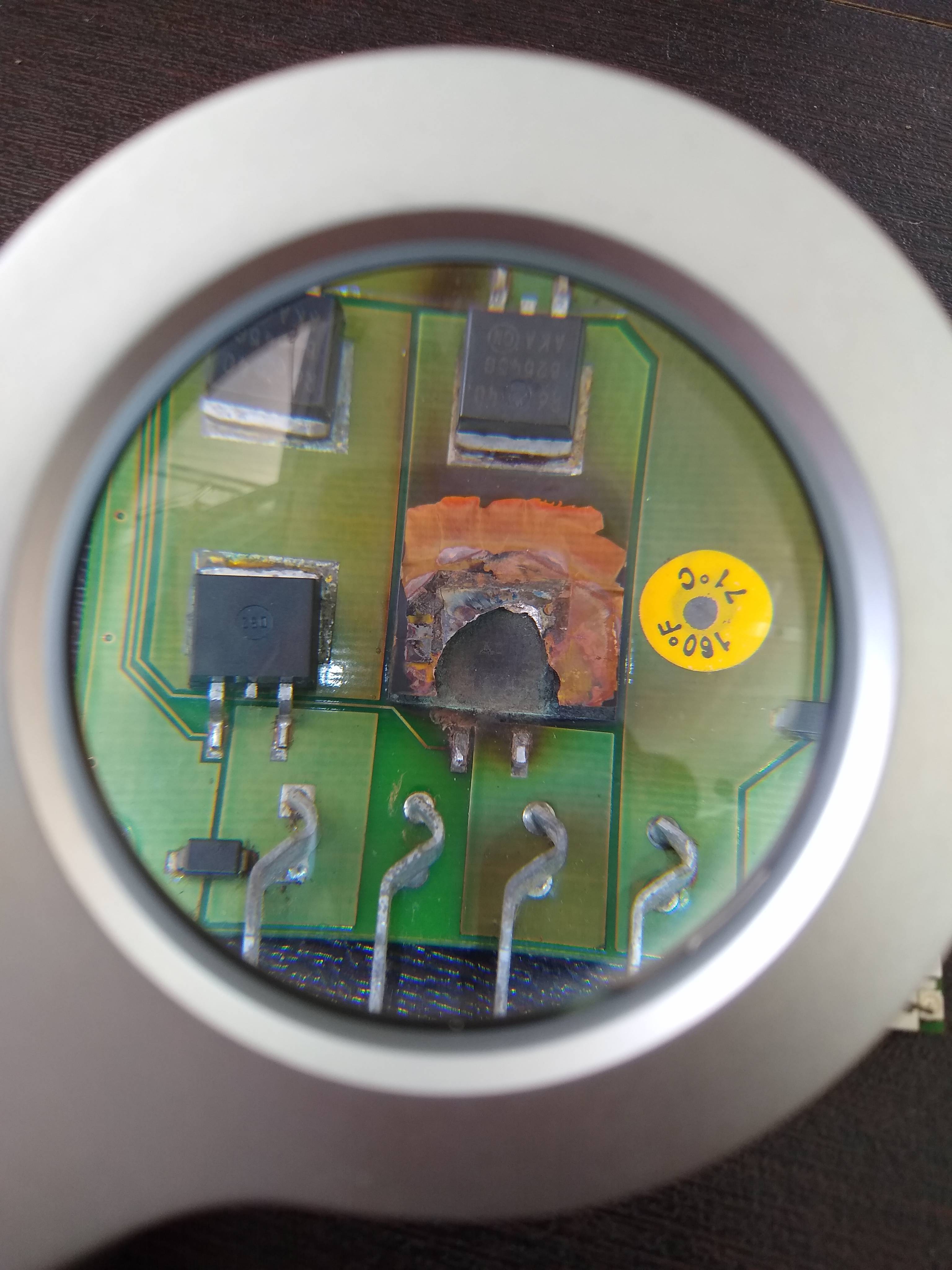
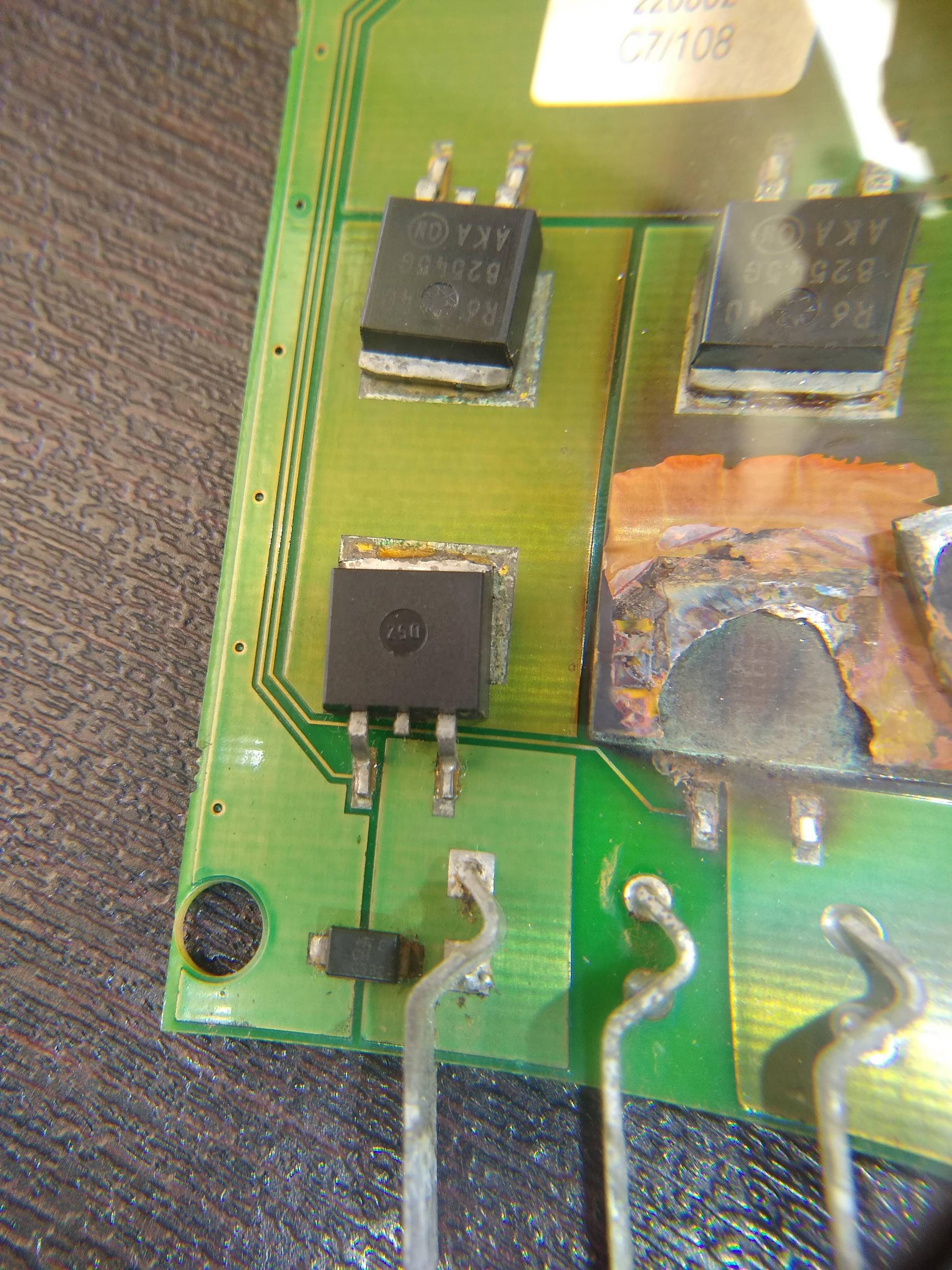
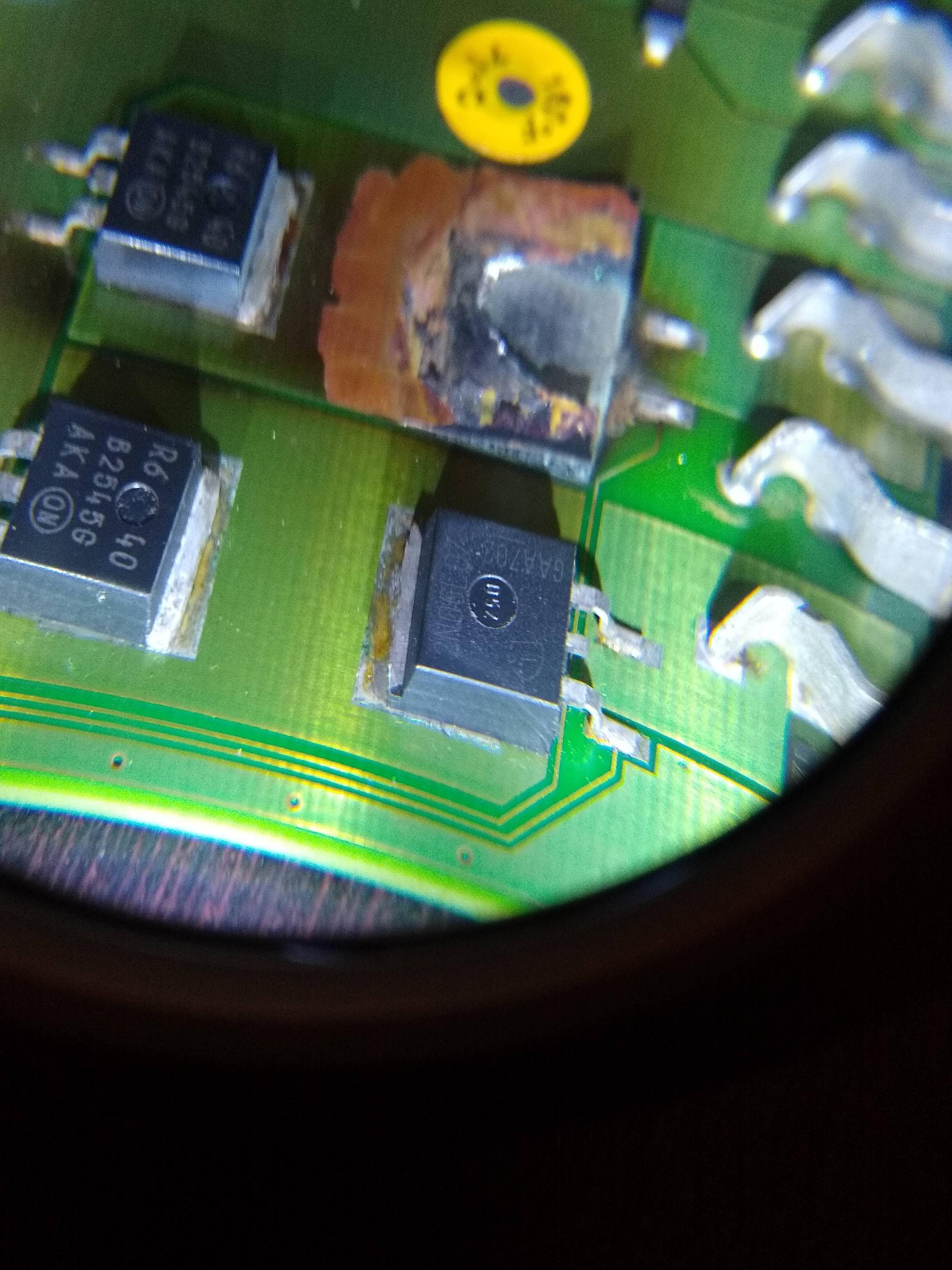
The attached pictures show the circuit board in a small 260 Watt PWM solar controller that I inherited on a sailboat I've owned the past 8 months. This is a secondary charge controller used to maintain engine starter batteries. This controller has one (relatively) unique feature in that it has the ability to charge 2 separate battery banks from a single solar input, and at one time it was hooked to 2 starter batteries. Only one battery charge circuit ever worked, and when I pulled it apart it became clear why. The MOS-FET on the second battery connection was overloaded at some point and is kaput.
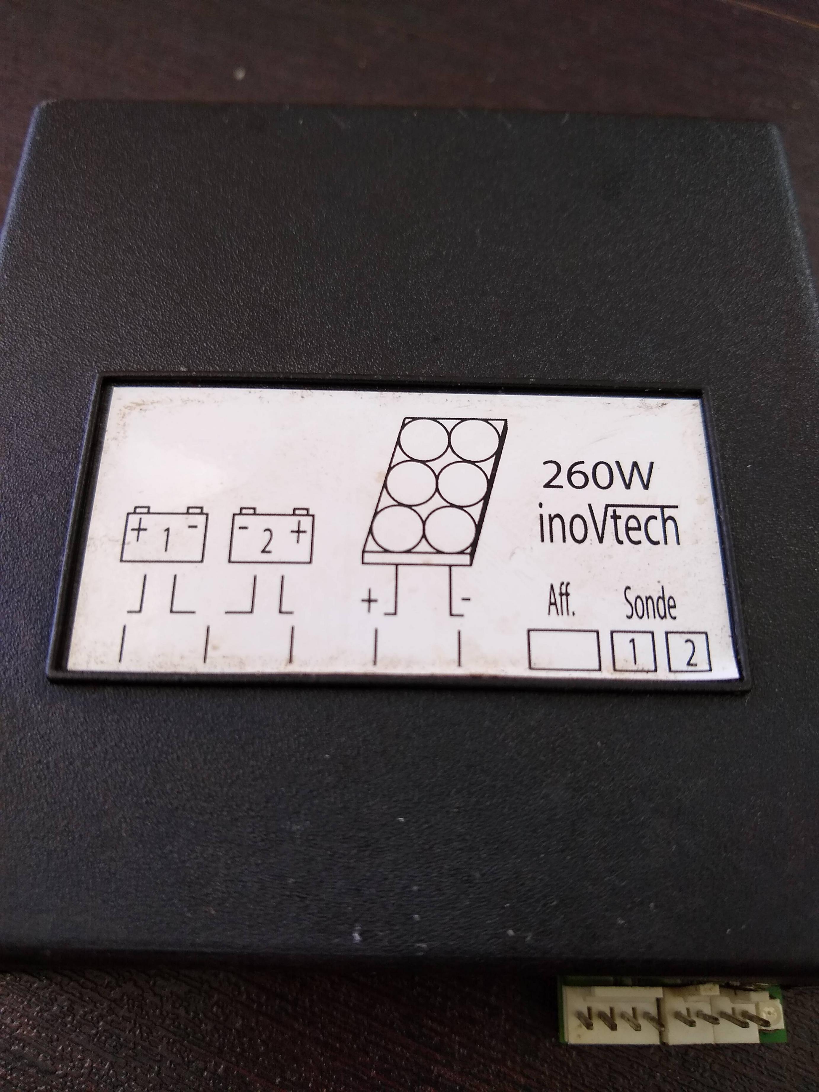
The charge controller is an inhouse brand (InovTech) of a French motorhome, caravan and accessory company. I've not managed to find any specifications or detailed documentation online, but I assume the 260 Watt rating is the maximum nominal 12V solar panel input power.
EDIT to add: for what it's worth, I have this charge controller hooked to a single small 20 watt flexible solar panel used solely to maintain starter batteries. Usually this controller will see a max of 1.5 amps. The overload happened with a previous owner, and the boat now has a separate, much larger 1000 watt MPPT controller for the house battery bank.
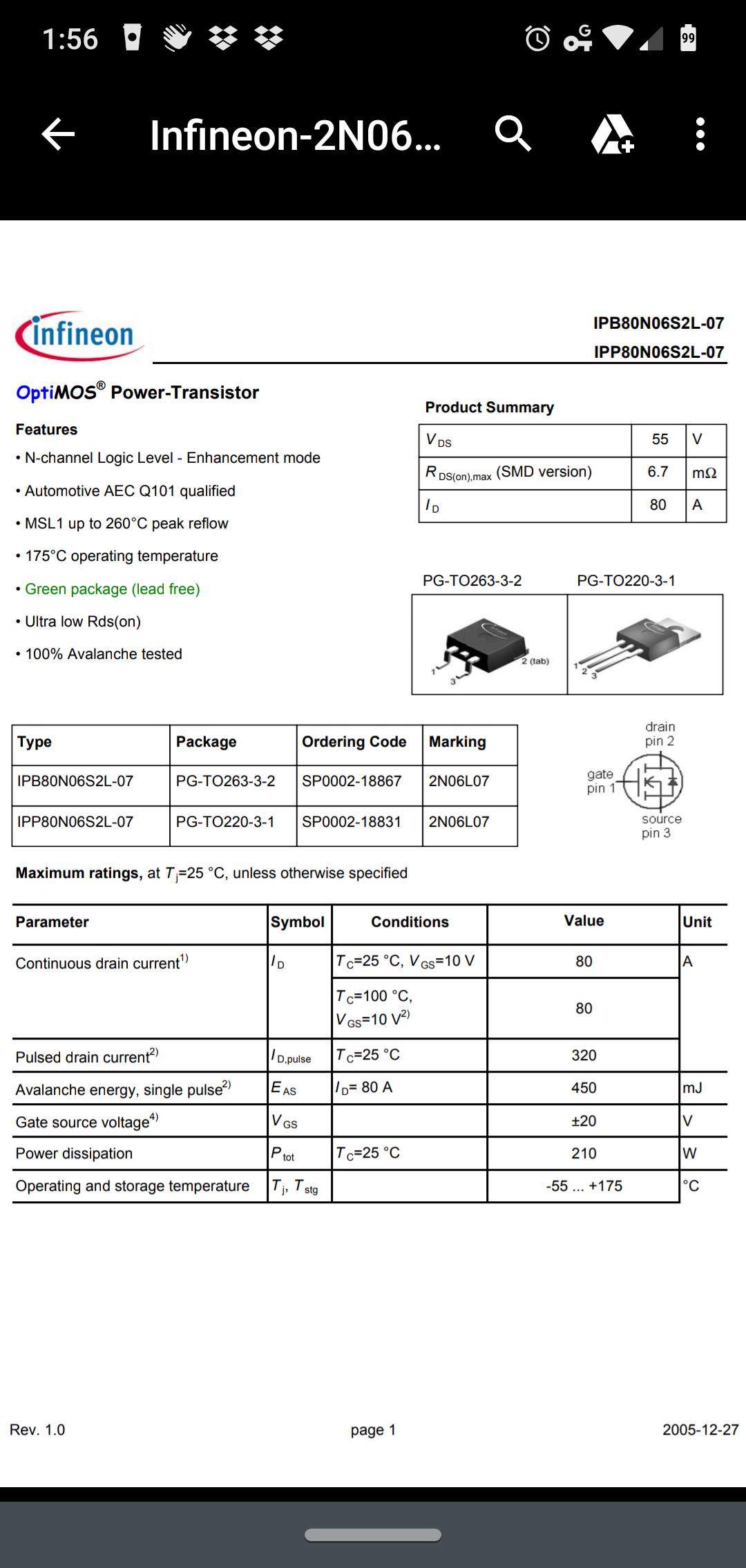
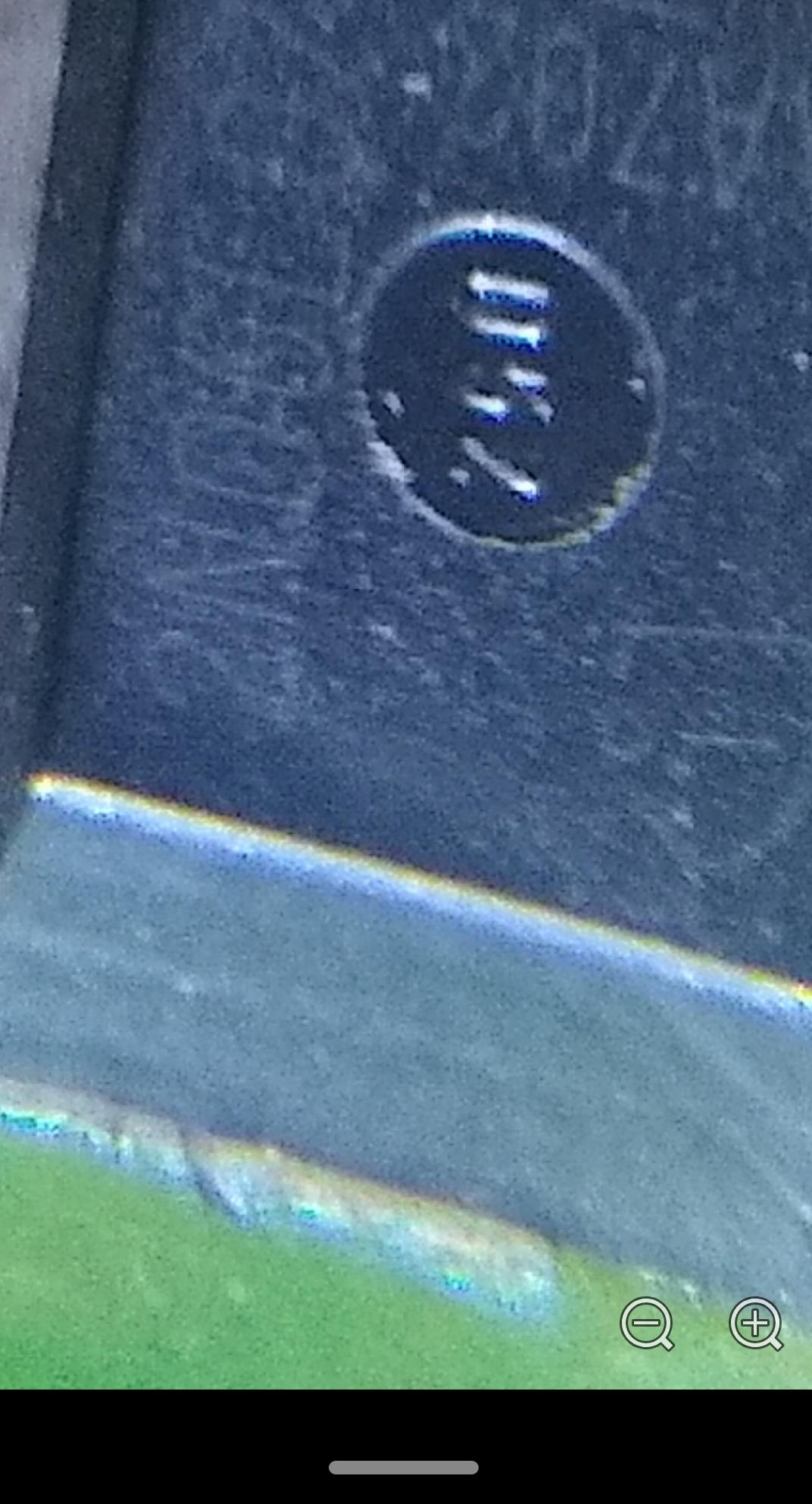
It is very faint, but the burnt out MOS-FET is marked 2N06L07 and GAA702.
So my first question: is the N-channel Infineon IPB80N06S2L-07 below a match? It is marked 2N06L07. This MOS-FET is rated for a maximum voltage of 55V, a maximum current of 80A, BUT it's power dissipation is only 210 Watt.
https://www.infineon.com/dgdl/Infin...n.pdf?fileId=db3a304412b407950112b43232455757
Second question: to the experts on this forum, do you think this circuit board can be salvaged if I replace the MOS-FET? And possibly attach an external heat sink?
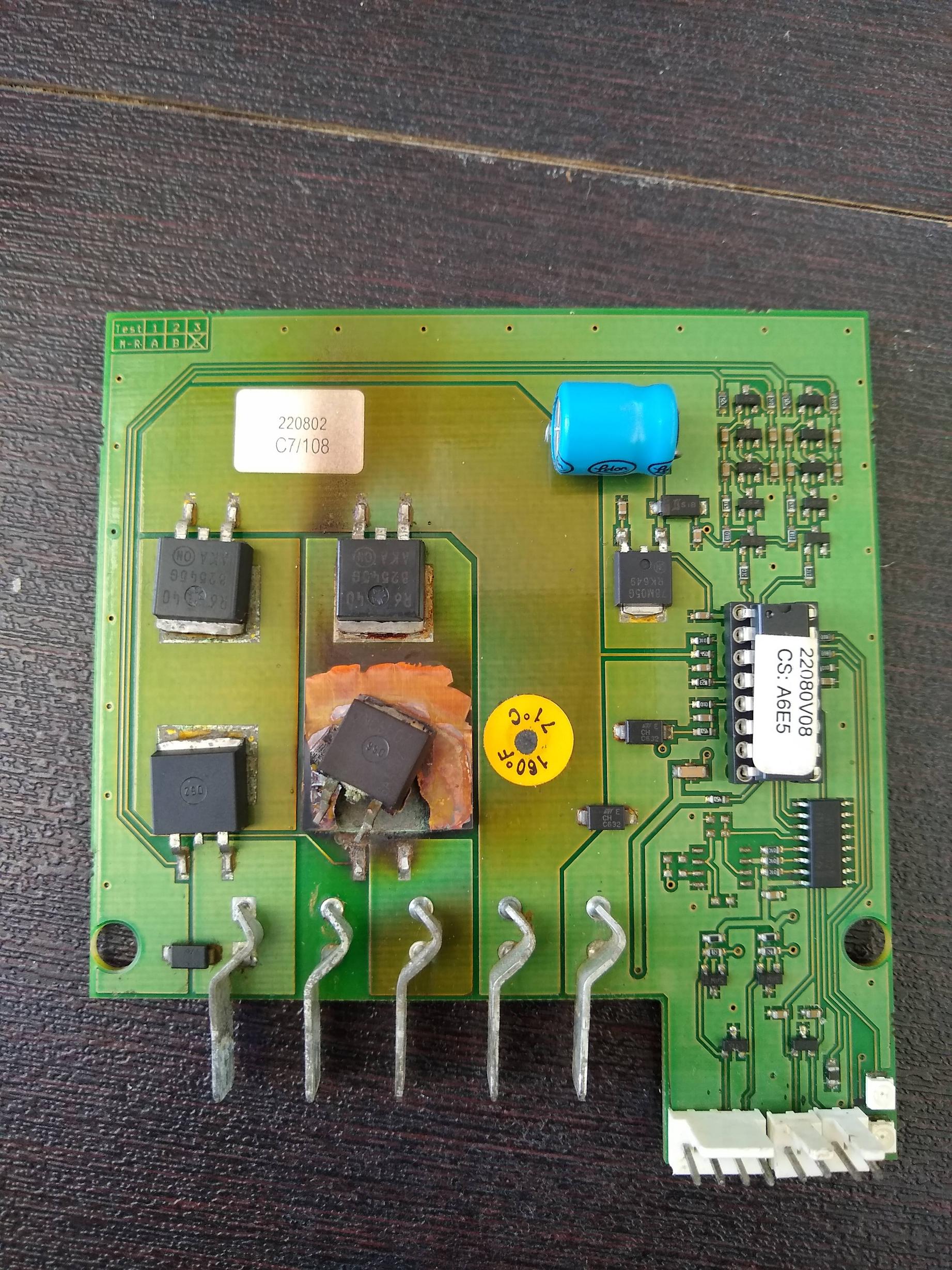
The attached pictures show the circuit board in a small 260 Watt PWM solar controller that I inherited on a sailboat I've owned the past 8 months. This is a secondary charge controller used to maintain engine starter batteries. This controller has one (relatively) unique feature in that it has the ability to charge 2 separate battery banks from a single solar input, and at one time it was hooked to 2 starter batteries. Only one battery charge circuit ever worked, and when I pulled it apart it became clear why. The MOS-FET on the second battery connection was overloaded at some point and is kaput.
The charge controller is an inhouse brand (InovTech) of a French motorhome, caravan and accessory company. I've not managed to find any specifications or detailed documentation online, but I assume the 260 Watt rating is the maximum nominal 12V solar panel input power.
EDIT to add: for what it's worth, I have this charge controller hooked to a single small 20 watt flexible solar panel used solely to maintain starter batteries. Usually this controller will see a max of 1.5 amps. The overload happened with a previous owner, and the boat now has a separate, much larger 1000 watt MPPT controller for the house battery bank.
It is very faint, but the burnt out MOS-FET is marked 2N06L07 and GAA702.
So my first question: is the N-channel Infineon IPB80N06S2L-07 below a match? It is marked 2N06L07. This MOS-FET is rated for a maximum voltage of 55V, a maximum current of 80A, BUT it's power dissipation is only 210 Watt.
https://www.infineon.com/dgdl/Infin...n.pdf?fileId=db3a304412b407950112b43232455757
Second question: to the experts on this forum, do you think this circuit board can be salvaged if I replace the MOS-FET? And possibly attach an external heat sink?
Last edited: