-
Categories
-
Platforms
-
Content
You are using an out of date browser. It may not display this or other websites correctly.
You should upgrade or use an alternative browser.
You should upgrade or use an alternative browser.
Scroll to continue with content
KrisBlueNZ
Sadly passed away in 2015
I wasn't quite right about the reason for the overshoot in post #40. I think the right explanation is:
At startup, there is no conduction in the optocoupler until the output rail reaches its target voltage. With the emitter output configuration, with the error amp in circuit, the capacitor from COMP to VFB will limit the rate of rise at the COMP pin, because as COMP rises, a rising voltage is coupled into VFB which causes the error amp to oppose the increasing COMP voltage by making its open collector transistor conduct. This will slow down the rising voltage at COMP and will provide a kind of soft start.
With the collector output configuration, COMP will rise rapidly at startup, and delays in the feedback loop will cause the overshoot at the output.
If this explanation is right, it should be easy to see the difference in the rate of rise of the output voltage with the two circuits. The output voltage should rise much more slowly in the emitter output circuit than in the collector output circuit. You should be able to see a roughly corresponding signal at the COMP pin for each design as well.
After these explanations, it seems difficult to say that "Common collector" has any advantages in achieving improved transient response over the "common emitter"......
However, I don't believe that linear.com could have been wrong, and I think there must be some other explanation why in fact the CC is "very slightly" better than CE.
The cascode is explained on page 9 of this...
http://www.onsemi.com/pub_link/Collateral/AND8273-D.PDF
I spell "cascode" like that because otherwise the web page changes it to "cascade".
The following concerns using a casc0de stage to improve opto feedback bandwidth.....
http://www.onsemi.com/pub_link/Collateral/AND8273-D.PDF
...on page 9, just above fig13, it does say that the cascode is used so that "looking" up from the opto's collecter, the impedance seen is less as its "looking" into the emitter of a BJT biased ON.......from this you would then conclude that CC is better than CE.....because even though CC doesn't involve a cascode stage, it DOES involve looking up from the collector of the CC'd opto and seeing a low impedance, because from the opto collector in CC, you "look" up and sees the supply rail, which is a low impedance to AC.
Thus I conclude that in fact, CC is better than CE for getting improved transient response and easier facilitation of good gain and phase margins.
I don't believe its the miller effect as such, but still I believe CC is better than CE....I certainly have linear.com in my corner...(the LT4430 datasheet on about page 16)
So I would conclude that if the cascode improves bandwidth over a CE connection...then so too must the CC connection
However, I don't believe that linear.com could have been wrong, and I think there must be some other explanation why in fact the CC is "very slightly" better than CE.
The cascode is explained on page 9 of this...
http://www.onsemi.com/pub_link/Collateral/AND8273-D.PDF
I spell "cascode" like that because otherwise the web page changes it to "cascade".
..right, so we are saying that there is still some "miller effect" in the optocoupler transistor even if it has no base resistor?I'm sure that's true. The reason is the reduced change in the voltage across the transistor in the optocoupler, which reduces the Miller effect greatly and causes much faster response in the optocoupler. This is the reason for the cascode design in the first place.
The following concerns using a casc0de stage to improve opto feedback bandwidth.....
http://www.onsemi.com/pub_link/Collateral/AND8273-D.PDF
...on page 9, just above fig13, it does say that the cascode is used so that "looking" up from the opto's collecter, the impedance seen is less as its "looking" into the emitter of a BJT biased ON.......from this you would then conclude that CC is better than CE.....because even though CC doesn't involve a cascode stage, it DOES involve looking up from the collector of the CC'd opto and seeing a low impedance, because from the opto collector in CC, you "look" up and sees the supply rail, which is a low impedance to AC.
Thus I conclude that in fact, CC is better than CE for getting improved transient response and easier facilitation of good gain and phase margins.
I don't believe its the miller effect as such, but still I believe CC is better than CE....I certainly have linear.com in my corner...(the LT4430 datasheet on about page 16)
So I would conclude that if the cascode improves bandwidth over a CE connection...then so too must the CC connection
Last edited by a moderator:
cascode
cascode
cascode
It's not the web site
And what's your bet about the oucome? From reading your statement above, you still seem to be betting that there's going to be a difference.
So you're sure?
cascode
cascode
It's not the web site
And what's your bet about the oucome? From reading your statement above, you still seem to be betting that there's going to be a difference.
but still I believe CC is better than CE
So you're sure?
The linear.com app note definitely and undoubtedly states that CC is better than CE.
So I have to say, that for whatever reason it is, I still believe it....because of the impedance seen of the rail being low (from an AC point of view)
My bet is on CC better than CE...ie easier to get improved transient response and improved phase and gain margins
It must be my computer then putting cascade instead of cascOde.
Cascode
cascade
cascade
Pages 16, 17, 18 of the following are so lucidly written that I cannot help but believe it, they also present the mathematical basis for CC and CE comparison
http://cds.linear.com/docs/en/datasheet/4430fc.pdf
conclusion, I say CC is better
I almost find myself thinking Steve has discovered this, and has found the reason for it too.
If so, I guarantee all that the result will be a revelation for the world of SMPS.....most of this type of info is so secret that it just doesn't exist in books.
Last edited:
davenn
Moderator
It must be my computer then putting cascade instead of cascOde.
Cascode
cascade
cascade
no its you typing a 0 ( zero) instead of lower case o
as I said in my edit of your post above, learn to proof read your writing before you post
throughout all your posts you are often typing 0 instead of o
")
Dave
Last edited:
KrisBlueNZ
Sadly passed away in 2015
Thanks for the link to the LT4430 data sheet. As usual for Linear Technology, the applications section is full of interesting and useful information.
The last paragraph on page 17 says "The common-collector configuration eliminates the Miller effect of the output transistor's collector-to-base capacitance and generally increases achievable loop bandwidth." I don't think that's right. I don't see how it can be. But I'm also aware that the Linear Technology folks are far better qualified than I am, and they have obviously done some thorough research in the process of designing this device and providing the huge amount of guidance on power supply design in the applications section. And it should have been checked by several people at LT. So like Steve, I'm willing to revise my opinion if someone can answer our (Steve's and mine) objections.
An optocoupler with no base connection is closest to a common emitter amplifier. The input source is the photocurrent from the collector-base junction, and it causes current to flow into the base-emitter junction, forward-biasing the transistor. Whether the load resistor is on the emitter side of this two-terminal device, or the collector side, makes no difference to the relative voltages, currents, and capacitances in the transistor.
The last paragraph on page 17 says "The common-collector configuration eliminates the Miller effect of the output transistor's collector-to-base capacitance and generally increases achievable loop bandwidth." I don't think that's right. I don't see how it can be. But I'm also aware that the Linear Technology folks are far better qualified than I am, and they have obviously done some thorough research in the process of designing this device and providing the huge amount of guidance on power supply design in the applications section. And it should have been checked by several people at LT. So like Steve, I'm willing to revise my opinion if someone can answer our (Steve's and mine) objections.
I doubt it's the web site. I've never had a problem with it. Do you have some kind of automatic spell correction feature installed in your browser?I spell "cascode" like that because otherwise the web page changes it to "cascade".
I believe the Miller effect is relevant, and will apply equally whether the output is taken from the collector or the emitter...right, so we are saying that there is still some "miller effect" in the optocoupler transistor even if it has no base resistor?
Right so far.The following concerns using a casc0de stage to improve opto feedback bandwidth..... http://www.onsemi.com/pub_link/Collateral/AND8273-D.PDF
...on page 9, just above fig13, it does say that the cascode is used so that "looking" up from the opto's collecter, the impedance seen is less as its "looking" into the emitter of a BJT biased ON.......
No, because the performance differences between common emitter and emitter follower stages are only relevant when the input signal is applied to the base WITH RESPECT TO THE POWER RAILS. This requires a connection to the base. With an optocoupler with no connection to the base, there is no difference between collector output and emitter output, because the signal (the photocurrent) is always applied between the base and emitter (this is the closest analogy), whether the emitter is grounded or not.from this you would then conclude that CC is better than CE.....because even though CC doesn't involve a cascode stage, it DOES involve looking up from the collector of the CC'd opto and seeing a low impedance, because from the opto collector in CC, you "look" up and sees the supply rail, which is a low impedance to AC.
An optocoupler with no base connection is closest to a common emitter amplifier. The input source is the photocurrent from the collector-base junction, and it causes current to flow into the base-emitter junction, forward-biasing the transistor. Whether the load resistor is on the emitter side of this two-terminal device, or the collector side, makes no difference to the relative voltages, currents, and capacitances in the transistor.
No. There's a good reason why cascode improves the bandwidth. The voltage change across the collector-emitter of the phototransistor is greatly reduced. This is the whole idea of the cascode circuit, whether it's used with a phototransistor or not. The reduction in voltage change across the transistor means that there is less voltage change to be coupled from the collector to the base through the Miller capacitance. It makes the Miller capacitance almost irrelevant. The phototransistor is being used as a variable current sink, driving a load with very low impedance (the common base stage). The effect of the Miller capacitance of the other transistor (common base stage) is also hugely reduced because the base grounded for AC signals. (Usually a decoupling capacitor is added between base and ground, if the base is driven from a voltage divider as shown in the ON Semi app note).So I would conclude that if the cascode improves bandwidth over a CE connection...then so too must the CC connection
Steve,
As a chemist, I put my faith in experiments.
I am dying for the answer, and it is getting late.
John
Edit: I just searched on Miller effect and common collector. Apparently, the lack of Miller effect with CC (and CB) is accepted by many departments (see slide 4 and following): http://www.seas.upenn.edu/~ese319/Lecture_Notes/Lec_11_Miller_Effect_08.pdf
Last edited:
I've written to linear.com via their technical assistance web form....not sure if they will look into this though, I think I should have linked this thread in...
I am now swaying in favour of what Kris said, because that is convincing, but then, so too was the linear.com statement.
Jpanhalt, thanks for the link, tho' its been proffered here that miller is equally small with optos in CC or CE.
By the way, whilst on the subject of Opto feedback in SMPS's, heres two opto-isolated SMPS's (attached is the schematic in pdf and jpg and LTspice sim) -both with "CE" feedback....except one has the opto diode connected to vout, and the other has it connected to a fixed, regulated bias voltage.
Which method do you think more easily facilitates achievement of fast transient response whilst maintaining good gain and phase margins?
I seem to think that the one with opto to vout certainly seems better for stopping start-up overshoot, because the RC across the R(LED) connects right in to the opto diode(?)
Basso covers these on pages 285-295 but doesn't say which is best for stability and transient response
Also the following covers both ways but again doesn't compare them
http://www.onsemi.com/pub_link/Collateral/TND381-D.PDF
(slides 31 and 36)
Attachments

Last edited:
conclusion, I say CC is better
I almost find myself thinking Steve has discovered this, and has found the reason for it too.
If so, I guarantee all that the result will be a revelation for the world of SMPS.....most of this type of info is so secret that it just doesn't exist in books.
OK, so knowing that I had done the experiment, eem2am was still prepared to bet on some magic effect that makes a 2 terminal device sense whether a resistor is connected to one as opposed to the other.
There is a slight difference between the circuit I used and the one I proposed. This is mostly so I could get an inverted signal into my scope to enable me to use the add function. The practical upshot is that one or signal appear inverted in some shots, but it doesn't affect the result.
So firstly, what do the signals look like side by side...
These are not inverted. Since we're measuring the coltage across the transistor, the falling edge represents the transistor turning on and the rising edge the (slower) turn off.
There is no obvious difference. If you can detect one, then I challenge you to tell me which one is "common collector" and which one is "common emitter"
I should point out that I swapped the optos around and, whilst I don't have photos of it, the traces are visually identical.
OK, that may not be enough. I have an "add" function on my scope, and since one signal is actually inverted, I can add them together and see the resulting waveform (yes, in the image above one signal is inverted in the scope).
Because I'm
OK, so here is the signals and the difference. And this is as good as it gets for you eem2am. There appears to be a difference between the 2 cases. very small, but measurable.
So the obvious thing to do is to swap the optos around to see if it caused by differences in the devices.
And here we are. The effect is much smaller. And it's fair to say that the difference between the 2 devices swamps out any difference which might remain.
I did measure the resistors used, and they were slightly different in value. I *could* swap them over to see if this also has an effect, but I didn't last night because it was getting late.
I think this shows no evidence that would suggest to me that the transistor works any differently (without a base connection) if the series resistor is connected in series with the collector or with the emitter.
Your assertion remains unproven. (i.e. I think I've shown that you're wrong in believing it)
Attachments


Thankyou for this -very much appreciated, I certainly think linear.com would be interested to see your results. The LT4430 datasheet is now very intriguing on pages 16, 17 and 18.
I am of course, impelled to believe that there is no difference between CE and CC connection after seeing your experiment.
I am of course, impelled to believe that there is no difference between CE and CC connection after seeing your experiment.
I certainly think linear.com would be interested to see your results.
I doubt it.
The LT4430 datasheet is now very intriguing on pages 16, 17 and 18.
Not really. I think they were using "Miller effect" in the same way that they were using CE and CC.
Their point was that with one configuration the transistor was able to turn on sufficiently to affect the desired change faster in one circuit than in the other.
The speed of switching can be seen as a symptom of the Miller effect, and I think that this was how they used it.
What you read into it was that the optocoupler itself behaved differently in one configuration rather than the other *due* to the placement of the resistor, when it was the differing operating conditions which were (far more likely) the cause.
I am of course, impelled to believe that there is no difference between CE and CC connection after seeing your experiment.
I don't want to to feel compelled, I would prefer that you understand.
If you want to understand, you need to go back to the Vishay document and read carefully about all of the factors which affect the switching speed of an optocoupler. You then need to see how many of these apply in the two circuits you've shown us.
I believe you have these circuits simulated. This should enable you to see the voltages and currents (I mentioned before that Vce and Ic are important) and compare them -- are these differences predictive of slower switching?
If you're going to use optocouplers, this information may be critical. OK, so you followed a lead which was a dead-end. It's better to find out about that before you build it into a design.
From long hard experience, I've learned a few things that are relevant to this thread.
1) There's lots to learn, but are very few secrets in electronics. If the configuration (CE vs. CC) made a huge difference, someone would have seen it. It would be in all the datasheets and there would be parts "optimised for CC use", or "optimised for CE use". The fact that there isn't any of this should first suggest that there's something else you haven't considered.
2) Appeal to authority. You need to know when to do this and when not to. Sure, rely on datasheets (but remember they're not perfect). Consider reliable (but not perfect) the advice of experts. But, take neither as proof of correctness. If something is seriously called into question, you need to be able to find evidence and give consideration to its weight. And go back to your theoretical knowledge to see if you can explain it. Even better, do an experiment.
3) Know what the null hypothesis is and who has the burden of proof. In general "No it doesn't" reigns until "Yes it does" can provide strong enough evidence. In this case I did not provide evidence that this affect does not exist, I was simply unable to show that under a carefully considered set of conditions it does.
4) Stick to your guns. If it's not proven to your satisfaction, then it;s not proven to your satisfaction. You might have been right in this case. If you had acceded to my argument whilst still unconvinced, neither of us would have learned anything. (In this case I learned a lot more detail about optocouplers, and I have to thank you for that).
5) Be prepared to eat humble pie. If I had found there was an effect, I would have done so.
If you search for a thread about Vbe breakdown you'll find I was wrong, I did an experiment, and I showed the effect. I then did further study and found out the actual reason (knowing what to Google initially would have saved me much embarrassment).
https://www.electronicspoint.com/emitter-base-breakdown-t257654.html
Arouse1973
Adam
I did a similar experiment with a BFX43, base left open. Maybe I had the setup wrong but I followed what Steve was doing apart from having two power supplies.
what do you think.
Thanks
Adam
what do you think.
Thanks
Adam
Attachments


Arouse1973
Adam
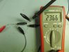
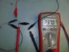
Also did another experiment if your interested with a OP593 which shows an increase in current out of the emitter compared to the collector. There was a small debate about this also. This device does not have a base lead.
Thanks
Adam
Thanks
Adam
Attachments
KrisBlueNZ
Sadly passed away in 2015
It looks like you're comparing the turn-on time with the turn-off time. In the second picture you have the scope connected with reversed polarity across the load resistor. This means that the first part of the scope trace, from which the edge rises upwards, corresponds to the phototransistor being ON, and the rising edge corresponds to it turning OFF. The first picture shows the opposite. The Miller capacitance and charge storage are the reasons why the transistor turns OFF more slowly than it turns ON.I did a similar experiment with a BFX43, base left open. Maybe I had the setup wrong but I followed what Steve was doing apart from having two power supplies.
A difference of 4 µA in a 2370 µA signal is 0.17%. This could be easily caused by your power supply warming up, or your battery discharging slightly, or the imperfect repeatability of your multimeter, or the device warming up, or other factors.Also did another experiment if your interested with a OP593 which shows an increase in current out of the emitter compared to the collector. There was a small debate about this also. This device does not have a base lead.
It looks like optoisolators do actually isolate after all!
Arouse1973
Adam
It looks like you're comparing the turn-on time with the turn-off time. In the second picture you have the scope connected with reversed polarity across the load resistor.
hi Kris, thanks for the feedback.
I did this because I didn't have a an invert function on the scope. Both traces were captured as I connected the power to the IR emitter by hand, so this can't be turn off can it?
A difference of 4 µA in a 2370 µA signal is 0.17%. This could be easily caused by your power supply warming up, or your battery discharging slightly, or the imperfect repeatability of your multimeter, or the device warming up, or other factors.
I did an earlier experiment wit the BFX43 and used a precision meter, this showed and increase of 10uA. But the meter is to big to get in the picture. The PSU had been on all morning as I had been using it for other work.
Thanks
Adam
KrisBlueNZ
Sadly passed away in 2015
No, if that's true, then it can't. But if you're running the phototransistor side from a 9V battery (which is fine and a good idea), it's easy to repeat Steve's test. Just connect the scope across the load resistor in each case. Here are the node lists for each configuration.I did this because I didn't have a an invert function on the scope. Both traces were captured as I connected the power to the IR emitter by hand, so this can't be turn off can it?
Collector output ("common emitter"):
node 1: battery positive; load resistor top end; scope probe
node 2: load resistor bottom end; optocoupler collector; scope ground
node 3: battery negative; optocoupler emitter.
Emitter output ("common collector" or "emitter follower"):
node 1: battery positive; optocoupler collector
node 2: optocoupler emitter; load resistor top end; scope probe
node 3: battery negative; load resistor bottom end; scope ground.
When you apply current to the optocoupler's LED, you should see the scope indication rise from 0V to somewhat less than +9V. This corresponds to the phototransistor turning ON. If both curves are the same, you have confirmed Steve's experiment.
You know there's no electrical connection to the phototransistor in an optocoupler, right? The phototransistor circuit is completely isolated and self-contained.I did an earlier experiment wit the BFX43 and used a precision meter, this showed and increase of 10uA. But the meter is to big to get in the picture. The PSU had been on all morning as I had been using it for other work.
Do you think a measurement difference of 0.42% can be explained by the factors I listed in my last post, or do you think it points to a real phenomenon? Can you borrow a second multimeter so you can measure both currents simultaneously?
at this point, I am not sure if it affects the application even if there *is* a tiny amount of base current (with no base resistor).
Steve's graphs tend to show me that there is going to be no difference between the CC and CE connection methods in the application of SMPS opto feedback.
So it does look like the only way to get improved stability at faster transient response with opto feedback is to use a cascode stage (windows 8 is still writing 'cascade')
In the post #49 I show two other ways to connect up optos to get more facilitated stability and response.
Of course, we all know that light is an EM wave......we also know that the entire concept of electric current flowing in a circuit is nonsense...but at low frequencies, it is an approximation that we can get away with....at microwave, we have to consider it as it really is, a transition of EM waves.
So if EM waves are coming from the base, then to me that is like an electric current anyway, so I believe that Arouse1973 is right in many ways.
The concept of a "flow of charge" as you know is actually totally wrong, energy flow in all electric circuits is actually by EM waves which flow along and around and partly inside, the circuit conductors.However, if you have a simple "model" of behaviour, (even if its wrong) and you can use it to design something well, then why not stick with it...and we do...."electric current being a flow of charge"
Last edited by a moderator:
Arouse1973
Adam
So it does look like the only way to get improved stability at faster transient response with opto feedback is to use a cascode stage (windows 8 is still writing 'cascade')
In the post #49 I show two other ways to connect up optos to get more facilitated stability and response.
Of course, we all know that light is an EM wave......we also know that the entire concept of electric current flowing in a circuit is nonsense...but at low frequencies, it is an approximation that we can get away with....at microwave, we have to consider it as it really is, a transition of EM waves.
So if EM waves are coming from the base, then to me that is like an electric current anyway, so I believe that Arouse1973 is right in many ways.
What I have been saying all along, perfect.
BTW I have emailed a Physics contact I have in Australia to get an unbiased accurate answer.
I also have a few contacts at Linear Tech, unfortunately I can't email Jim Williams as he has passed away sadly. But I will see if I can get another opinion.
Thanks
Adam
Also did another experiment if your interested with a OP593 which shows an increase in current out of the emitter compared to the collector. There was a small debate about this also. This device does not have a base lead.
So you're telling me that you have a series circuit where the current at one point differs from the current at another point. And to be clear, we are talking frequencies where the wavelength is HUGE compared with the size of the circuit (essentially DC).
Similar threads
- Replies
- 4
- Views
- 798
- Replies
- 0
- Views
- 617
- Replies
- 2
- Views
- 668
- Replies
- 2
- Views
- 926