Maker Pro
Maker Pro

Simple led circuit - to difficult for me

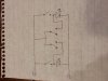
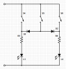
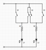
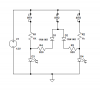
Hi, I haven't worked with electronics since high school almost 20 years ago. My son and I are building a simple circuit with three push button switches. One push button lights a blue led, another lights a red led, and the third push button lights both at the same time. I can figure out the two individual push buttons, but can't figure out how to wire the third so that it lights both, but doesn't cause the other two to light all three as well. Any help is appreciated. It's killing me that I can't figure this out. My 18 year old self would kick my ass right now. Thanks in advance
 
Double pole switch for the two and single pole for the others. When you press the double pole switch it can supply voltage to both. Connect both contacts of the other side together and connect them to the power and connect one of the poles to the output of one of the other switches. Connect the other pole to the output of the other switch. Easiest way if you only want to use switches.
Thanks Adam.
 
BJT logic

have transistor bjts in series with each light....there bases are pulled high so they are auto on
have other transistors so that these two are eith off or on, or on together.

a bjt biased on with its collector to another's base turns that one off...id jump on ltspice and just knock it around till it works as you want.
 

(*steve*)

¡sǝpodᴉʇuɐ ǝɥʇ ɹɐǝɥd
Moderator
Steering diodes are even easier. I don't have time to draw a circuit right now, but I will (if nobody beats me to it) a little later.

2 resistors, 2 LEDs, 2 diodes, and three switches (SPST is sufficient)
 
Steering diodes are even easier. I don't have time to draw a circuit right now, but I will (if nobody beats me to it) a little later.

2 resistors, 2 LEDs, 2 diodes, and three switches (SPST is sufficient)

Yep agreed will work just as well Steve. Didn't want to include diodes and possibly confuse things.
Adam
 
Adam, is this what you were getting at? Do you guys see any issues with the diagram? Thanks again. You all are great
 

Attachments

  • image.jpg
    image.jpg
    126.1 KB · Views: 124

(*steve*)

¡sǝpodᴉʇuɐ ǝɥʇ ɹɐǝɥd
Moderator
The main issue is that you don't have resistors in series with the LEDs.

The use of a DPST switch means you don't need steering diodes or any other logic.
 

(*steve*)

¡sǝpodᴉʇuɐ ǝɥʇ ɹɐǝɥd
Moderator
Here is the suggestion using the DPST switch:

attachment.php


And here is a version with SPST switches and diodes:

attachment.php


You need to determine the correct value for the resistors. Look in the tutorial section for https://www.electronicspoint.com/got-question-driving-leds-t256849.html. All you need to read is section 1
 

Attachments

  • TwoLEDs2.png
    TwoLEDs2.png
    8.3 KB · Views: 239
  • TwoLEDs1.png
    TwoLEDs1.png
    10.2 KB · Views: 207
Steve and Adam, thank you so much for your help!! I greatly appreciate it and so will my 6 year old when his "invention" is finished. You guys are great. Thanks again!
 
If you use the steering diode method, there's going to be a small, possibly unnoticeable brightness difference between single color and dual color due to the diode voltage drop. If it's a concern, just add a diode to each of the S4 and S6 switch lines to even it out.

It may be a moot point if you already plan to add trimmer resistors to adjust relative brightness or color mixing.
 
Last edited:
Top