Maker Pro
Maker Pro

Simple circuit for running and reversing a motor....

I have written a program on the comp to use my parallel port to control external devices like a motor. unfortunately, it can only give some 2.5 volts and for some reason (probably internal resistance) cannot run the motor independently.
I connected it to a transistor to amplify the current and used it. It works fine.
Now my question is this:
I need a circuit to make the motor run clockwise, and then when i alternate the output of the parallel port, i want it to run counter-clockwise. The parallel port will alternate between 1-0 and 0-1 so what can i do with this ?
I need to first amplify the current using the transistors, but i don't know where to connect the load (motor) !
Also, when the output is 0-0, it shouldn't run..... so theres a start button(1-0 or 0-1),an alternate button(which switches 1 for 0) and a stop button(0-0) from my parallel port.

Thanks.
 
whoa, that seems like a lot of work for such a simple task ! if my parallel port could chug out enough, i could've just used it by itself. It powers up red LEDs easily and alternates them fine..... Isn't there any way to amplify each output of my parallel port instead ?
So is there any way to convert my port's analog output to a digital one, amplify it using an external source, and just plug in my motor so that it can switch rotation modes with the press of a button like i did for the LED ?

Thanks
 
Hehe, hardly any more work than making a pizza from scratch..
The port is lacking umph by a factor of at least 100..
You can always use dedicated driver IC's.
 
what do you mean by dedicated driver ICs ? any chip names/numbers ? Will it be any easier... Cause the principal is sound:- amplify each parallel port output and connect it directly..

Thanks
 
There is a plethora of IC's and circuits out there, this isn't exactly a new concept. They come in a number of cases, from simple-to-use 8-pin DIP chips to large (complex) devices with cooling tabs. There's too many for me to choose one for you. Googling for "full bridge motor driver" will give you more answers than you might want. If you also add "parallell port" or "printer port" or "lpt port" to the search you'll find (a limited number of) pages discussing exactly what you're trying to do. If you find something interesting please do come back and ask if you're uncertain about it's applicability.
 
Great, i found something so simple it can't go wrong.. Just 4 transistors and i can easily understand the logic..... Here's it is:
Bolt_smokeless_Hbridge.gif


Now, this looks fine since my parallel port can supply to the base of a transistor easily. But i have one question. See those 1K ohm resistors connected to the base ? What purpose do they serve ? Can i do without them if my current output is low ?

Thanks.
(it will work right ?)
 

(*steve*)

¡sǝpodᴉʇuɐ ǝɥʇ ɹɐǝɥd
Moderator
Without the resistors you would effectively be shorting your power supply through the base-emitter junctions of the transistors -- that would be a bad thing. (and that's just the start of it)

If your current is very low you could increase the value of those resistors.

Since you're driving a motor, protection diodes for the transistors may be a very good idea (place a reversed biased shottky diode across the CE leads of each transistor).
 
Hello,
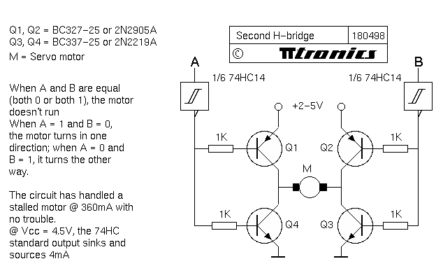
I ended up using this circuit that i adapted from the previous design i found:
circ20312.gif

(A and B are my parallel port inputs, and theres another line that connects to the port's ground)

It seems to work fine...

Now, moving on to the second phase which i have no idea about, can you direct me to any resources that deal with remote control ?
I want to control a motor(for now) from my laptop parallel port, remotely.....
I don't want to use IR cause of the limited range etc, but i do want to use radio. Unfortunately i have absolutely no idea how to go about this.

I understand the principles and concepts of radio transmission and pick-up but i don't know how to implement it...if there's any links, chip numbers or any sort of resources that could be of help to me, i would be thankful.


Thanks
 

(*steve*)

¡sǝpodᴉʇuɐ ǝɥʇ ɹɐǝɥd
Moderator
Ah, here's the problem. If this device is attached to your parallel port an the pins A and B are set to the wrong values, you could turn on Q1, Q2, Q3, and Q4 at once.

The results of that are likely to be less than marvellous for the transistors involved.

The other problem is that to turn on Q1 or Q2 you need to raise the base to a fairly high voltage. If your parallel port only uses 0 or 5V logic levels then these transistors will not saturate, the voltage drop across them will be quite high, the motor will get a lower voltage, and the transistors may get hot.

I would advise you to go with the circuit you suggested earlier. It is intrinsically safe as there is no combination of inputs that will fry your transistors. You can ignore the inverters if you like, and the parallel port *may* be able to deliver enough current to operate the H bridge.

The other thing I would add are protection diodes across the transistors.

Also, if you are connecting stuff to your parallel port, the last thing you want is to fry it. It may be very hard to replace if you do so. So be careful.
 
Last edited:
Hmm... If i am connecting only the base of each transistor to the parallel port output, then is it still possible to fry the parallel port chip ? I'm guessing there's no input voltage to the parallel port, just output, so theres no reason it should fry.....

Also, yes, you are right about the huge voltage drop. I thought that it was just a faulty transistor or two.... Is there any way to reduce this voltage drop and ensure transistor saturation with the only NPN setup? Because i know my parallel port offers very less current and about +3V....
I was told that a better alternative to my transistors are MOSFETs.... will they be any better ?
So, if i use the first circuit with PNPs and NPNs, there will be less of a voltage drop ? I don't understand why... Could you please explain ?

As for turning on all the transistors simultaneously, i'll stay away from that, my program to control the port won't allow that. (Thanks for that tip)

And one last thing...
Last edited by (*steve*); Yesterday at 04:54 PM.. Reason: you are eptheta! ???
Thanks.
 

(*steve*)

¡sǝpodᴉʇuɐ ǝɥʇ ɹɐǝɥd
Moderator
Last thing first :) I originally pointed you to a comment made by yourself, thinking that it was made by someone else. I corrected that with the observation that "you are eptheta!"

The way to avoid the large voltage drop is to drive the transistors transistors correctly. That means you need to be able to get the base more positive than the emitter (for NPN transistors). Depending on the saturation voltage (VCEsat), the base current, and the base resistor, this could quite easily require you to drive beyond the +ve supply rail (if you can't do this then the transistor may not be able to be saturated and the voltage drop across it will be higher). Note that I have seen H bridges designed the way your later circuit is designed, but I really don't like them as they also allow all transistors to be turned on at once.

In either case, you need to be able to bring the control voltage from rail to rail (at least). If you're using a higher voltage than your parallel port can put out (which you say is 3V) then you need some sort of buffer or level shifter to make it work properly. In the original circuit a schmitt trigger is shown which will give both a rail to rail swing, and transition from one state to the other very quickly.

Mosfets *may* be better, but they require gate voltages in the order of 5 to 15 volts -- at a minimum you're still going to need a swing of 5 volts. Transistors (especially darlingtons) have a relatively high VCEsat -- the voltage from collector to emitter when fully turned on. This may be between 1 and 2 volts. If you have 2 in series (which you do) then you could quite easily drop 2 to 4 (of perhaps 5) volts available for your motor. Mosfets often have a very low resistance (some measured in single digit milliohms) and will waste far less power at low current. For your circuit, it may be easier to run it off a higher voltage to allow for the voltage drop across the transistors.

Check out this page http://letsmakerobots.com/node/4593 it discusses H bridges and part way down the page is a circuit that uses 3 transistors per half bridge to ensure correct drive. This would be easily suitable for being driven by your parallel port. Note however that the transistors in the bridge are darlingtons.

The driver mentioned above could be used to drive mosfets in a similar arrangement too. A problem with mosfets is that it would be easier to have both turned on simultaneously while switching -- it can cause huge spikes on your power supply.

As for not turning on all the transistors at once, you may not be able to prevent it. Program bugs, or the sequence the parallel port goes through during the power up sequence of your computer, or a whole host of other things could cause it to happen. It is far better to have an inherently safe design than one which relies on what is essentially luck.
 
Alright...It's been a long time...
I've gotten past stage 1, that is getting this transistor H-bridge working from my parallel port and it does work just fine...
Now i need help on the second stage-- wireless control...
I wanted to set up a transmitter and receiver of say radio-waves so i can remotely control my motor from my laptop... Unfortunately, i have no experience with this type of project, so i'd like some help and suggestions..
-Is radio wave control an easy way of data transmission, or should i use something simpler but which has a decent range ?
-Could anyone suggest some links to info about constructing a receiver and generator ?
Thats all for now,
Thanks
 
Are you still using the circuit you posted where you are driving two NPNs each from two parallel port bits? If so, you have really not gotten past stage 1. You will have to come back and revisit it because the transistors will blow up. Might as well fix it now rather than come back to it later.

As Steve pointed out, if there is a code bug or computer crash you will have all the transistors on and they will not like it. Depending upon your power supply, you could do quite a bit of dammage.

You also do not have flyback diodes. Those are protection diodes across the collector and emitter of each of the transistors, installed "pointing up" in the schematic. Without them your transistors are seeing potentially serious flyback voltages and they will eventually fail from that.

Lastly, you are dropping a lot of power on the top transistors and they will over-heat and fail if you are running any amount of current. That said, you may not have much current because you are running your motors at about 2V. If the motors are barely crawling, you will not have much flyback either.

---55p
 
Acctually, I'm using 2 PNPs and two NPNs (according to the first diagram i put up) and i do have 2 diodes from the emitter to the collector of both transistors to prevent any back-flow. It works fine and the motor runs decently. I think it is fine the way it is.
Now i really do need help with part 2.... any suggestions ??
Thanks
 
I am assuming that you also have the 74HC14 in there as well and are running close to 5V.

You really do need 4 diodes, one on each of the transistors. For the two PNP transistors (the top ones) the cathode if the diode (the pointy end) needs to be connected to the + voltage. For the two NPN transistors, the anode needs to be connected to ground.

The diodes are not there to prevent "back flow" They are there to steer the energy in the motor to the power supply. When you stop driving the motor, the motor is still spinning due to inertia. It now becomes a generator and starts producing power. The diodes steer that power into the power supply. It is also called regenerative braking.

As for phase 2 of the project, I am not really sure what you are trying to do. Lets step back and start with the big picture, rather that getting into how you plan to accomplish it.

You have the motor connected to the parallel port of a PC. You have that working. What do you want to do next? Do you want to control it with another PC or a laptop?

---55p
 
Last edited:
Right, i have a motor connected to my parallel port on my laptop. I made a program on c++ to send +5V to the respective terminals. I now want to control the motor without the direct wire connection to my parallel port.
That is i want a wireless connection. So i will have 1 module connected to my port that transmits some data wirelessly, and another module on my motor that receives it and translates it into electrical signals..
Thats pretty much it....
 
If that is what your final goal was, you may have wasted a bunch of time doing what you have done so far. Much of what you have done may end up having to be thrown out and redone. All your C code is very specific to the PC and will not translate directly to the final implementation.

What you are looking for is a device that you can basically insert between the parallel port of the PC and the input of the motor that will replace the length of cable with wireless. I personally do not know of any such device, but you may be able to find something. The closest thing I can think of to get some ZigBee boards from one of a dozen or more manufacturers. You will have to build the network and make the boards part of the network. I think it can be done, but I am not 100% sure. I do know that it will be quite a bit of work and not the easiest way to do this.

If you were starting from scratch, I would connect a ZigBee module to the PC through the serial port or USB and then connect the motor to the other ZigBee module. Things will go much easier if you were talking serially (or USB) to one of the modules, because you can use that communication channel to setup your network and command the remote module to change its output pins.

Another option is to build up on what you have. Leave the motor connected to the PC and send commands to that PC from a remote PC via WiFi or BlueTooth.

I suggest you read up on ZigBee. Select some modules that you can buy and are in your price range. Understand the communications protocol for those modules and get back if you have any question after that.

---55p
 
Top