Maker Pro
Maker Pro

Sewing machine speed controller repair

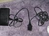
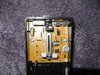
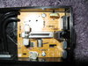
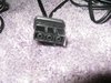
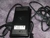
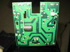
I have a used electronic speed controller(model N) from a brother sewing machine. Input voltage to controller is 120V but output voltage is nada, zip, zero. Does not matter if pressed to floor or not, still no voltage. I'm a nob at electronics but good at replacing components if problem(s) can be discovered. I do have a simple capacitor tester and all three tested ok within specs. Attached are pics of board. If someone could enlighten me as to further multi-meter tests to try I'd be eternally grateful
 

Attachments

  • IMG_5988 (2).JPG
    IMG_5988 (2).JPG
    527 KB · Views: 7
  • IMG_6000.JPG
    IMG_6000.JPG
    267.1 KB · Views: 9
  • IMG_6001.JPG
    IMG_6001.JPG
    816.5 KB · Views: 11
Correction, there is no voltage going to the board, only voltage coming from mains. I have continuity from pin 2 to neutral on board and continuity from pin 3 to line on board but voltage does not register either on pins 2 or 3 or on board solder points of line and neutral. Not sure what this means. Maybe cord is bad, maybe other board component? By pins 1,2,3, I mean the cord(see picture)
 

Attachments

  • IMG_5989 (2).JPG
    IMG_5989 (2).JPG
    271.8 KB · Views: 6
  • IMG_5993 (2).JPG
    IMG_5993 (2).JPG
    406.3 KB · Views: 5
Wondering if I need to place a load on pins 2 and 3 somehow, then test voltage? Forgot to mention that I no longer have the machine. I just want to know if speed controler is working.
 
Last edited:
No fuses to be found on this cheap board (looks to me as though they bypassed what was supposed to be a fuse and just put a wire across it?). i don't have a tungsten lamp - can i use 60 watt incandescent instead? (remember i'm a electronics knob :-(

I unscrewed the board and added a pic of back side of board. Do these types of speed controllers need a load to receive power from the mains, or could I have a component failure?
 

Attachments

  • IMG_6004.JPG
    IMG_6004.JPG
    772.8 KB · Views: 5
Last edited:
Sir whiteoutage . . . . .

Just two wires are being involved with the dimmer power control path in the submited explanation.
HOT AC line power comes down and passes thru the lamp then passes down into the dimmer as the PURPLE DOT path unitil it reaches the TRIAC power controller YELLOW RECTANGLE.

Other photo

As the foot switch rollers move to the right the speed / lamp intensity should increase.

First photo

The returm power path is made via the BLUE DOT path.
If no control, your placing of a jumper wire across the triac terminals marked with the RED bar should give full lamp brightness if there are no wiring problems.

If not . . . expect the need of replacement of previously mentioned YELLOW RECTANGLE triac . . a la . .most honnable . ..alex_teeeeeeeeeeeeeeee.

Thassssssssssssit . . .

REFERENCING . . . . . . . compliments of the DUMMY patrol . . . . buy their books . . . . .

3aheFLP.jpg


Kids in the back seat can cause accidents . . . . . . . . . accidents in the back seat cause kids.
 
Top