Maker Pro
Maker Pro

Servo or stepper? Help please!

Hey all, first post and new to most of this stuff as I am more of an automotive fabricator. I need to build something for shifting a sequential transmission forward and reverse electronically. I have an old electric push button shifter (see below) that has for some reason stopped working, but I’m trying to fix it if possible.
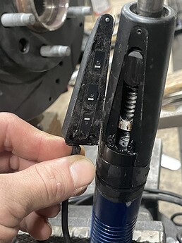


This uses a motor and a lead screw to create the linear motion, but it really is quite old technology. As you can see, there are micro switches that presumably reverse the polarity to return it to the middle after shifting. All this happens in about 50ms. The shaft is also broken, but because the motor no longer spins I am unable to pull it apart to see what type of motor they used. It is very powerful as well, probably 20 pounds of force if I was guessing. Only two wires going to the motor.

With today’s stepper motors and servo motors, what would be the fastest way of doing this? It would be nice if it could be cut down to around 20ms per shift. I have access to mills, lathes, and welding so I can definitely build whatever to make it work. The new version of this product is rotary based, though the time is still the same, and they are quite expensive. Plus I’m more of a diy guy anyway.

Any help would be greatly appreciated!!
 
Even at 50ms a servo or stepper is not going to have the power nor the speed.
Dc motor and worm drive like you already have is best and use optical encoder for position/direction via a small microcontroller.
 
Even at 50ms a servo or stepper is not going to have the power nor the speed.
Dc motor and worm drive like you already have is best and use optical encoder for position/direction via a small microcontroller.
Awesome to get an answer! Haha thanks. So would it be possible to do with an arduino then or would something more powerful be necessary?
Any chance you could recommend specs for the motor? Should I look for torque or speed or something in the middle?
 
It all depends on what you intend to use for a worm drive, what sort of reduction etc.
Remembering that you need power as well as speed but 20 milliseconds I would imagine be an almost impossible task in some respects.
 
So i just started looking at motors with encoders on them, found this one that might fit the bill, but need some help doing calculations to know for sure. (And no idea if this is the type of encoder that would work)
https://www.robotshop.com/ca/en/555-size-dc-motor-with-encoder-12v-8000-rpm.html

It states 6700rpm/0.4 kg.cm rated

Looking at lead screws, I get 8mm per rpm. If I need 1” of travel (estimate at this point), I need 3.175 rotations to achieve that. The stall torque is pretty high on this motor (2kg.cm), and since the first 1/3 of travel has no resistance, it could push pretty hard, but hopefully someone can tell me how to calculate that number.

There are of course many options for rpm so torque can be selected easily. Just need a baseline calculation to know what the top end of speed would get us. (While staying with a relatively small motor)
 
Last edited by a moderator:
If you need to have a moving force of some 20lb some so far unknown distance in 20 milliseconds you are going to need some serious hp, not a hobby motor.
Start at the output and work your way back...... hp is ability to lift a certain load a certain distance in a certain time.
Gear it down and the motor demand for power becomes less but the speed must increase proportionally.
 
I might start a new thread based on what I learned now. Just cut open the old unit, and shocked how small that motor is (27mm). But it uses a 15:1 planetary so could be around 600rpm?? Trying to clean the motor to see if it has any info on it. Maybe my torque estimates are way off. I remember it not really being possible to hold it if you pushed the button.

Speed might be a concession here. Looking at the website again, it says 2-3 shifts can be achieved in 1 second. Pretty sure I read the 50ms thing at one point, but who knows
 
Last edited by a moderator:
You could also start by measuring the breakaway torque required of the motor, use a short defined radius, wheel, pulley etc and a spring balance gauge in order to calculate initial torque.
 
Yeah it’s very difficult to measure the force though since it is dramatically easier when the engine is running/driving. I’ve been looking into the encodes for bit now, and not sure if that would actually be the better way to do it. I would probably have to play around with an arduino or something to see what is possible.

Can the polarity be reversed without a slow down time at a given amount of rotations?
If so, it might work fine, but finding exact center after each shift would be pretty important. Perhaps the transmission would help with that since it wants to be there anyway.
 
So I had a rethink on this project. I figure before I spend a ton of time machining the parts to make a linear version with lead screw etc, why not try a high torque lever version first. If it does not work, I only need to replace the motor and reprogram timing.
Anyways, posted a new thread in microcontrollers section as I’ll be needing help with the arduino selection and setup. Thanks for all the help guys, would still be looking for servo/steppers if not for you. Haha
 
That motor arrangement looks suspiciously similar to the old fashioned electric screwdrivers. Small motor, planetary gearset, high torque output etc. I have an old Black&Decker model that could turn a 747 engine over! (it's battery is knackered now though). If I wanted to make it work faster I'd be ok with doubling the supply voltage to the motor (it's actually rated at 3.2V and would probably be ok at 12V for short bursts).

If it was originally 'assembled' then it will come apart - never failed when I've been faced with taking something apart!
 
Top