You're right. Which made me realize it has to be something I did.
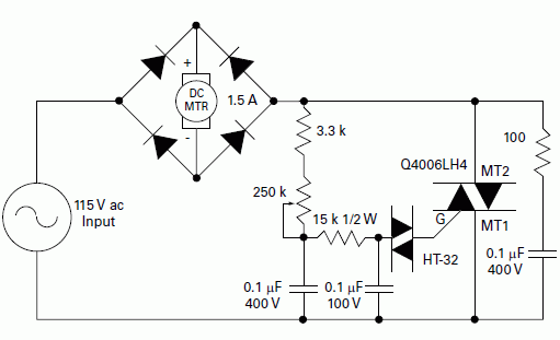
And it was. I forgot to attach the negative side of the capacitors to the negative bus. Stupid.
Minder, thank you so very much. You are the only reason I got this working!
Learned a lot about DIACs, TRIACs and some more about resistors and capacitors.... And a a good lesson was learned about paying attention and dilligence.
Last edited:


