If this works at all, it is as a shunt regulator.
It is possibly that the three phase AC source has a high enough impedance that a shunt regulator is satisfactory.
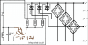
When the zener diode conducts enough, all three AC phases are shorted to the + bus. Each AC phase is released when that phase's current nears zero.
Note that the diagram utilizes triac symbols, not SCR symbols, for the three power devices. The BTA26 is, in fact, a triac:
http://www.st.com/st-web-ui/static/active/en/resource/technical/document/datasheet/CD00002264.pdf
Perhaps triacs might be the thing to use, as most SCRs wll not turn on to negative gate signals.
I believe that the TIP120 NPN transistor is shown connected backwards: The collector is shown going to the - bus, the emitter is positive. It is unlikely to work very well connected this way.
The TIP120 will live longer with a resistor in series with its base. The zener diode would also be happier. As the circuit stands, there is a low impedance path through the zener and transistor between the + and - buses.
The circuit may have difficulties if the AC frequency very much exceeds 50 to 60Hz. Most triacs are intended for AC line/mains frequency operation. Also, we might expect the impedance of each AC phase to be very inductive. So, there may be problems getting the triacs to "let go" once they are fired.
Is this a circuit "off the internet"? You might provide a link to any source for it.
It would be interesting to know something about the "engine stator", and the intended DC load.
Ted