Maker Pro
Maker Pro

Schottky diode input protection

Hi,

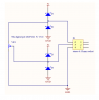
I am using a pair of schottky diodes to protect the input lines to a digital potentiometer.
The digital potentiometer is powered by the same 5volt line as the microcontroller that drives it via SPI, and the same 5volt line as the schottky diodes.

There is a small voltage at the anode/cathode junction about 50mV when I use BAT54S, and about 150mv when I use 1N5817.

I wonder why that is so, and how to stop it from happening.

thanks
 

Attachments

  • input protection.png
    input protection.png
    18.8 KB · Views: 205

(*steve*)

¡sǝpodᴉʇuɐ ǝɥʇ ɹɐǝɥd
Moderator
It may be caused by leakage through the diodes.

If you just connect a pair of diodes to +5v and gnd, do you see the same thing? If you place a 47k resistor across your meter leads (to reduce the input impedance) does the voltage disappear?

Is this voltage causing a problem, or is it an unexpected observation?
 
thanks steve, it is not causing a problem that I am aware of, it is just unexpected. I first noticed it when I connected the diodes for input protection because I was no longer able to read the resistance with a multimeter, due I suppose to the mV mucking up the meter.

The voltage at the wiper increases the further the wiper is moved away from ground. The voltage at the other end of the dig pot reduces to about 25mV when the wiper meets it.
47K across the probes reduces the voltage to about half.
Yes a pair of 1N4001's gives me about 20mV.

Maybe it is not a problem but I wanted to be sure. and I wonder why it is different for the 5817 Versus BAT54S.
I have seen a similar circuit in a commercial product and there is no voltage at the junction, though the micro and digital pot are using different supplies.
 

(*steve*)

¡sǝpodᴉʇuɐ ǝɥʇ ɹɐǝɥd
Moderator
Sounds like leakage through the diodes.

You would have to disconnect the input to confirm its not coming from there.

The 50k pot is loading the output down. Placing it in parallel with another 47k and having the voltage drop by half suggests the source has a pretty high impedance (which would match leakage, amongst other things)
 
I see. Seems ok then. But I think maybe I have not done this correctly. What I wanted to do was prevent greater than 5 volts being applied across the potentiometer, because the digital pot datasheet says that if the voltage across it is more than its VCC, then damage will occur.

But this dual diode I have implemented seems to prevent excessive voltage as in ESD, much like the IC probably already has built in. Is what I need then perhaps just some 5v zener diodes, and also the dual schottky solution as well?
 

Harald Kapp

Moderator
Moderator
The dual Schottky diode method is a classic one. It is the same principle used by the input protection of most ics. It should suffice.
5 V zener diodes aren't accurate enough to prevent a small overvoltage but not to let current flow in normal operation.
 
Schottky's can be a bit leaky. Try replacing them with 1N4148 or similar which was the go-to device for this purpose for many years.
 
Top