Hi everybody. Hope you had a great time over Christmas and my best wishes for all of you in 2019.
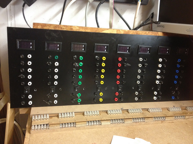
Wishing to get ahead with my project of implementing what I call 3rd generation panel:
It is a panel that offers me ways to connect my experiments to a choice of voltages. To the right of the first 4 columns, you can guess there to be a hole, 5 mm diameter next to the switch, same to the left of the switch in those 4 columns. My goal is to have 5 mm diameter RGB LED that shines in the color of the corresponding column. I still have to color some using Revell colors.
The voltages for the columns right to left are:
+24 VDC
+12 VDC
+ 5 VDC
+ 3.3 VDC
- 5 VDC
-12 VDC
The most right column is reserved i.e. to connect the battery pack I am making for my sailboat model,
12 LiFePO4 batteries connected in series which means the voltage will be between approx. +40 VDC and +24 VDC, depending if the batteries are full or unloaded to the tolerable minimum.
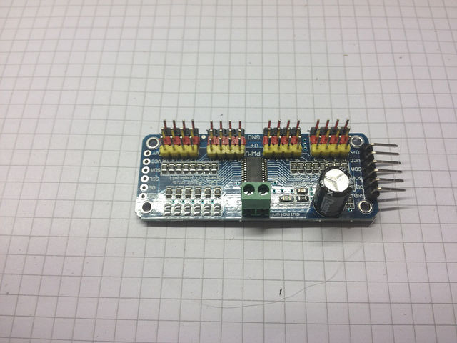
The circuitry I am planning to develop starts from the above-shown circuitry to feed RGB LEDs. The RGB LED I did purchase has a common cathode pin. As I am going to have 8 RGB LED in my panel this means I will have to feed 8 x 3 = 24 PWM to define the color in which each LED shines. As the Raspi ZERO W has a too limited number of pins to supply 24 PWM I am using 2 of this PCA9685 board were each of the can generate 16 PWM locally:
Here a picture of the rear of the panel front:
Until I found out that my RGB LED do not have a common anode but a common cathode pin and trying to see what devices would be proper to handle the RGB connections taking into account that a supply voltage of +24 VDC and up to +40VDC would require resistors of pretty high power. The 1/4 W SMD resistors would be OK for the lower voltages, but not for those 2 higher supply voltages.
I had planned to follow the circuitry above but replacing the 5 VDC shown there to come out of the Raspi by feeding the "positive pole" of the column. So I had planned to feed each of the RGB LED by connecting it to the receptacles above the switch. So the switch in the "ON" position, receptacles above the switch get their positive connected to the power source and the RGB LED is powered. Switching the switch to the "OFF" position and the RGB LED would be OFF.
Now my questions:
1. How does the circuitry change from the above-shown drawing?
Is it that I do have to connect GND to the cathode pin of the RGB LED and replace the GND connections in the drawing of the BC547 with the "Positive pole?
Or would I have to use PNP transistors in replacement for the BC547?
Would I have to connect the ground line of each voltage colon to the switch so that the RGB LED and the receptacles above the switch, so far I had planned to connect the positive poles to the switch to disconnect the receptacles above the switch and the RGB LED?
2. This question is related to my need to reduce the voltage fed to the RGB LED using a switched DC-DC converter to 5 VDC so I could use the 1/4 W SMD resistors. Also, the heat generated when a resistor is used to limit the maximum current through the LED to 20 mA would be intolerable.
Is it OK to also reduce the negative voltages, -12 VDC and -24 VDC using one of ma DC-DC switched converters by connecting the converter to GND which is the higher voltage and the "positive poles" here -12 VDC and -24 VDC? This voltage reductions, -12VDC to -5 VDC and -24 VDC to -5 VDC would be used exclusively for feeding the corresponding RGB LED and not the other receptacles to the transistor?
I hope I have been able to have given you the background information for my questions. I have not advanced my soldering work between the receptacles of the panel due to this questions I need to resolve upfront.


