3rd click counter clockwise maintains the .047 cap to the 5 way-terminal
and I will quote my library book on this--common emmiter circuit description
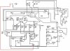
"Figure 7-5 is a schematic of a generic NPN common-emmitter circuit.
Capacitor C1 presents a short circuit to the AC signal, placing the emmitter at signal ground(but not nessesarily DC ground). resistor R1 gives the emitter a small positive DC voltage with respect to ground. The exact DC voltage at the emitter under no-signal conditions depends on the value of R1 and also on the base bias, determined by the ratio of the values of resistors R2 and R3. the Base Biase can range from 0v(ground potential) all the way up to the supply voltage, in this case 12v DC. Normally you'll want to set the no-signal base biase a couple of volts positive with respect to ground.
Capacitor C2 isolates or blocks DC from the input while allowing the AC signal to get through. capacitor C3, blocks DC at the output while letting AC signal pass. engineers call capacitors, such as C2 and C3 blocking capacitors. Resistor R4,keeps the output signal from shorting through the power supply while nevertheless, allowing a positive DC voltage to exisst at the collector.
A signal enters the circuit through C2, where it cuases the base current Ib to vary.

Small fluctuations inIb cause large variations in Ic. this current passes through R4, superimposed on the DC flowing through R4, passes through C3 to the output terminal..."
then there is this "DID YOU KNOW" box in the book that says...
An emitter follower circuit won't amplify signals, but it can help to provide isolation between two different parts of an electrical system. engineers call this sort of isolation circuit a
buffer."